


35
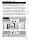
Connecting AV Components
—Continued
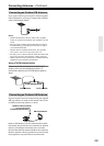
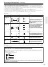
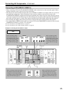
• When connecting a VCR to the TX-NR1000/TX-NR5000E, make connections for video and audio signals. Before
making connections, refer to page 30 for correct connections.
• This section shows the connection example when you use VIDEO 2 or VIDEO 3 as an input. In this case, you do not
need additional configurations. When connecting to other terminals within the same terminal section on the
TX-NR1000/TX-NR5000E, configure the audio input assignment in the Audio Assign sub-menu (See page 94), the
video input assignment in the Video Assign sub-menu (See page 95), the audio output assignment in the Audio Out-
put Assign menu (See page 91), and the video output assignment in the Video Output Assign menu (See page 92).
• You can change the display name for the input source to represent the actual connected device (See page 97).
• For a model without a HDMI terminal, when you connect a VCR to the COMPONENT terminals, be sure to use the
COMPONENT terminals to connect a TV or projector.
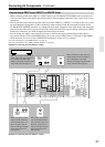
*For more information on the HDMI interface, see page 43.
*For more information on the i.LINK (AUDIO) interface, see page 40.
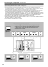
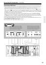
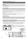
Example for connecting with the VIDEO 2 as input
Connecting a VCR (VIDEO 2, VIDEO 3)
REMOTE
CONTROL
MAIN
ZONE
3
ZONE
2
OUT
IN
FRONT
L
CENTERFRONT
R
SURR BACKR
(
ASSIGNABLE
)
SURR BACKL
(
ASSIGNABLE
)
SURR
R
SURR
L
IR
12V
TRIGGER
OUT
RS
232
A B C D F
G
H I J K L
A
C
B
D
E
200mA MAX.
100mA MAX.
100mA MAX.
100mA MAX.
100mA MAX.
“Net
-
Tune”
is
a
trademark
of
Onkyo
Corporation.
ETHERNET
(
Net
-
Tune
)
22
11
66
55
44
3 3
22
11
C D
DIGITAL IN DIGITAL IN
OPTICAL COAXIAL
OUT
SBR SBL
SR SL
SUB C
FR FL
SBR SBL
SR SL
SUB C
FR
FL
E
MULTI
-
CH
IN
1
MULTI
-
CH
IN
2
AUDIO IN
1
3
2
1
PH
2
3
9
8
7
6
5
4
4
5
LR RL
OUT
LR
LR
R L
F
G
L
IN
1
IN
2
HDMI, the HDMI logo
is a trademark
or registered
trademarks of HDMI
Licensing LLC.
OUT
HDMI
S
VIDEO VIDEO
IN IN
IN
1
IN
2
3
2
1
Y
P
B
PR
COMPONENT
VIDEO
IN
3
I
6
5
4
Y
P
B
PR
2
1
4
3
S VIDEOS VIDEO VIDEOVIDEO
OUT OUT
OUT
1
J
Y
P
B
PR
Y
P
B
PR
COMPONENT VIDEO
IN
4
OUT
2
K
ANTENNA
FM
75
AM
G
H
GND
AUDIO OUT
ANALOG
DIGITAL
COAXIAL
AUDIO OUT AUDIO OUT
AUDIO IN VIDEO IN
Y
P
B
PR
COMPONENT
VIDEO (RCA)
R
L
ANALOG
AUDIO IN
AUDIO OUTAUDIO OUT
VIDEO OUTVIDEO OUT
VIDEO IN
S VIDEO
IN
AUDIO IN
R
L
ANALOG
AUDIO OUT
S VIDEO
OUT
VIDEO
OUT
AUDIO OUT
DIGITAL
COAXIAL
VCR
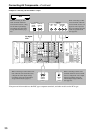
When connecting to other
audio terminals within the
same terminal section, config-
ure the audio input settings
accordingly using the Audio
Assign sub-menu (See page
94).
When connecting to other audio termi-
nals within the same terminal section,
configure the audio output settings
accordingly using the Audio Output
Assign sub-menu (See page 91).
When connecting to other
video terminals within the
same terminal section, config-
ure the video input settings
accordingly using the Video
Assign sub-menu (See page
95).
When connecting to other video ter-
minals within the same terminal
section, configure the video output
settings accordingly using the Video
Output Assign sub-menu (See page
92).
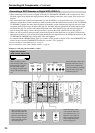
For digital
VCR