


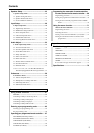
7
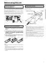
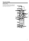
Setting the voltage selector
(Worldwide models only)
Worldwide models are equipped with a voltage selector so that you
can set your TX-SR800 to conform with local power supplies. Be
sure to set this switch to match the voltage of the power supply in
your area before plugging in the unit.
Determine the proper voltage for your area: 220-230 V or 120 V. If
the preset voltage is not correct for your area, insert a screwdriver
into the groove in the switch and slide the switch all the way to the
top (120 V) or bottom (220-230 V), whichever is appropriate.
Installing the remote controller batteries
1. Remove the battery compartment cover by pressing it
and sliding it in the direction shown by the arrow
below.
2. Insert two AA (R6 or UM-3) batteries into the battery
compartment. Carefully follow the polarity diagram
(positive (+) and negative (–) symbols) inside the
battery compartment.
3. After the batteries are installed and seated correctly,
replace the compartment cover.
Notes:
• Do not mix new batteries with old batteries or different kinds of
batteries.
• To avoid corrosion, remove the batteries if the remote controller
will not be used for a long time.
• Remove dead batteries immediately to avoid damage from
corrosion. If the remote controller does not operate smoothly,
remove the old batteries and replace them both with two new AA
batteries.
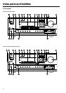
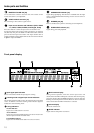
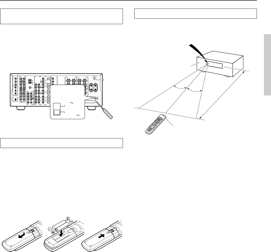
Using the remote controller
Point the remote controller toward the remote control sensor. The
STANDBY indicator lights up when the unit receives a signal from
the remote controller.
Notes:
• Make sure that the remote control sensor is not subject to strong
light such as direct sunlight or inverted fluorescent light for it
may prevent proper operation of the remote controller.
• Using another remote controller in the same room or using the
TX-SR800 near equipment that uses infrared rays may cause
operational interference.
• Do not put objects on the remote controller. Its buttons may be
pressed by mistake and drain the batteries.
• Make sure the audio rack doors do not have colored glass.
Placing the TX-SR800 behind such doors may prevent proper
remote controller operation.
• If there is any obstacle between the remote controller and the
remote control sensor, the remote controller will not operate.
Before using this unit
321
30˚
30˚
Remote control sensor
STANDBY indicator
TX-SR800
Approx. 16 feet
(5 meters)
AUDIO
VIDEO
S VIDEO
MONITOR
OUT
R
L
IN
IN
IN
IN
IN
ZONE 2
DVD
VIDEO 1
VIDEO 2
VIDEO 3
VIDEO 4
AUDIO
VIDEO
S VIDEO
COMPONENT
VIDEO
Y
P
B
P
R
OUTPUT
INPUT 1
Y
P
B
P
R
INPUT 2
Y
P
B
P
R
R
L
OUT
OUT
OUT
I
R
IN
OUT
REMOTE
CONTROL
PHONO
DIGITAL
INPUT
PRE OUT
DIGITAL
OUTPUT
OPT
2
1
2
3
FRONT
SUB
SURR
R
L
AUDIO
R
L
CD
TAPE
R
L
AUDIO
1
3
GND
SURR
BACK/
ZONE 2
IN
OUT
COAX
R
L
MULTI
CH
INPUT
FRONT
SUB
SURR
SURR
BACK
CENTER
R
L
R
L
AM
FM
75
VOLTAGE
SELECTOR
220
-
230V
120V
OPT
FRONT SPEAKERS
L
RL
R
SURR SPEAKERS
R
L
SURR BACK/
ZONE 2 SPEAKERS
CENTER SPEAKER
AC
OUTLETS
SWITCHED
TOTAL 100W MAX.
AV RECEIVER
MODEL NO.
TX
-
SR
800
CENTER
ANTENNA
4 OHMS MIN. OR
6 OHMS MIN.
/SPEAKER
CAUTION
:
SPEAKER
IMPEDANCE
SEE
INSTRUCTION
MANUAL FOR
CORRECT
SETTINGS.
120V
VOLTAGE
SELECTOR
220-230V
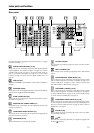
SEND/LEARN indicator