


19
TX
-
SR800
S VIDEO AUDIO
VIDEO L R
DIGITAL
VIDEO
5
INPUT
R
L
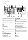
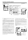
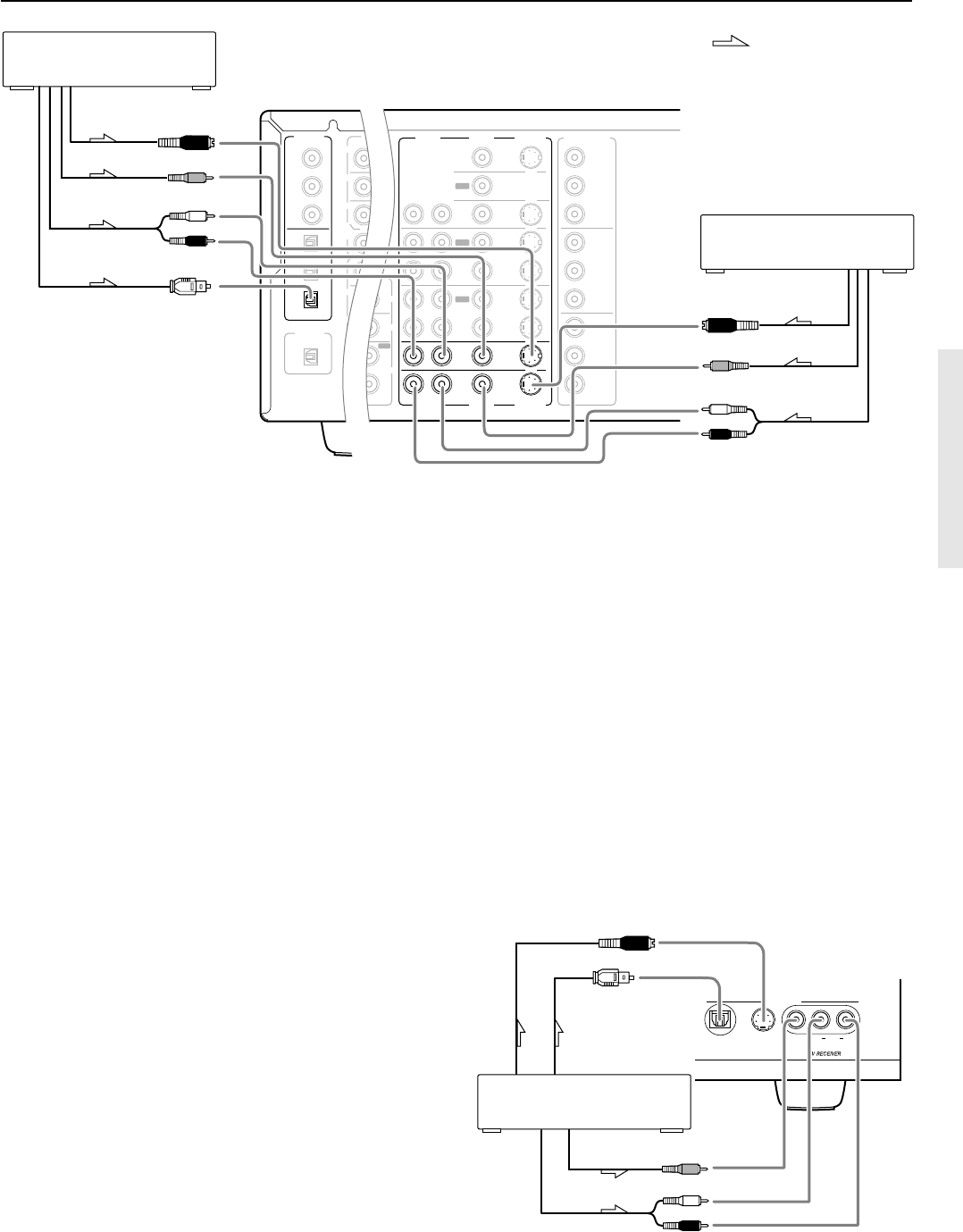
Connecting to Audio/Video equipment
S Video output
Digital output
(optical)
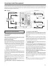
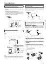
10. Video camera/ Video game
(VIDEO 5 INPUT)
Video output
Analog output
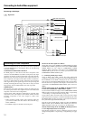
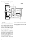
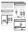
8, 9. Connecting a satellite tuner, television, or settop box
(VIDEO 3 or 4)
Using an RCA video cable, connect the video output jack
(composite) of the device to the VIDEO 3 (or 4) VIDEO IN jack of
the TX-SR800. Or if the device has an S video output jack, connect it
to the VIDEO 3 (or 4) S VIDEO IN jack of the TX-SR800 using an S
video cable. Or if the device has component video outputs, connect
them to one of the banks of COMPONENT VIDEO INPUT jacks on
the TX-SR800.
With the initial settings of the TX-SR800, the VIDEO 3 and 4
input sources are set for the COMPONENT VIDEO INPUT 2
jacks.
If you connect the device to the COMPONENT VIDEO INPUT 1
jacks, this must be changed at Setup Menu → Input Setup → Video
Setup → Component Video (see page 48).
Using an RCA audio cable, connect the audio output jack of the
device to the VIDEO 3 (or 4) AUDIO IN jacks of the TX-SR800.
Make sure that you properly connect the left channel to the L jack
and the right channel to the R jack.
If the device has a digital output, connect it to either the DIGITAL
INPUT COAX jack or DIGITAL INPUT OPT jack of the TX-
SR800 depending on the type of connector on the device.
With the initial settings of the TX-SR800, the VIDEO 3 input
source is set for digital input at the OPT 3 jack.
If the digital connection is made at a different jack, this must be
changed at Setup Menu → Input Setup → Digital Setup (see page 46).
With the initial settings of the TX-SR800, the VIDEO 4 input source
is not set for digital input. If you are connecting a digital component,
these settings must be changed at Setup Menu → Input Setup →
Digital Setup (see page 46).
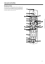
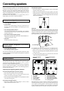
PRE
SUB
SURR
R
GND
SURR
BACK/
ZONE 2
R
FRONT
SUB
SURR
SURR
BACK
R
R
DIGITAL
INPUT
DIGITAL
OUTPUT
OPT
OPT
2
1
2
3
1
3
COAX
MONITOR
OUT
R
L
IN
IN
IN
IN
IN
ZONE 2
DVD
VIDEO 1
VIDEO 2
VIDEO 3
VIDEO 4
COMPONENT
VIDEO
Y
P
B
P
R
OUTPUT
INPUT 1
Y
P
B
P
R
INPUT 2
Y
P
B
P
R
C
SP
R
PHONO
O
L
CD
TAPE
L
O
IN
AM
FM
75
NNA
4 OHMS MIN. O
6 OHMS MIN.
/SPEAKER
CAUTION
:
SPEAKER
IMPEDANCE
SEE
INSTRUCTION
MANUAL FOR
CORRECT
SETTINGS.
OUT
AUDIO
VIDEO
S VIDEO
AUDIO
VIDEO
S VIDEO
L
OUT
OUT
OUT
: Signal flow
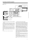
8. Settop box, video camera
(VIDEO 3)
S Video output
Video output
Analog audio
output
Digital audio output (optical)
9. Satellite tuner or television
(VIDEO 4)
S Video output
Video output
Analog audio
output
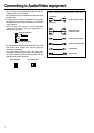
10. Connecting video camera, etc. (VIDEO 5 INPUT)
Using an RCA video cable, connect the video output jack
(composite) of the device to the VIDEO 5 VIDEO jack of the TX-
SR800. Or if the device has an S video output jack, connect it to the
VIDEO 5 S VIDEO jack of the TX-SR800 using an S video cable.
Using an RCA audio cable, connect the audio output jack of the
device to the VIDEO 5 AUDIO jacks of the TX-SR800. Make sure
that you properly connect the left channel to the L jack and the right
channel to the R jack.
If the device has an optical digital output, connect it to the VIDEO 5
DIGITAL jack of the TX-SR800.
The VIDEO 5 digital input is fixed to the OPTICAL input on the
front panel.
R (red)
L (white)
R (red)
L (white)
Front panel