


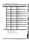
8.3 Wiring Precautions the Part which Matches the EMC Directives
8.3.1 Method to connect the power wire and ground wire
8 - 10
1
OVERVIEW
2
SYSTEM
CONFIGURATION
3
PERFORMANCE
4
NAMES OF
THE PARTS AND
THEIR SETTINGS
5
ROUGH
PRE-OPERATION
PROCEDURE
6
HANDLING
7
MAINTENANCE AND
INSPECTION
8
EMC DIRECTIVE
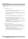
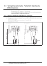
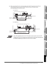
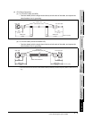
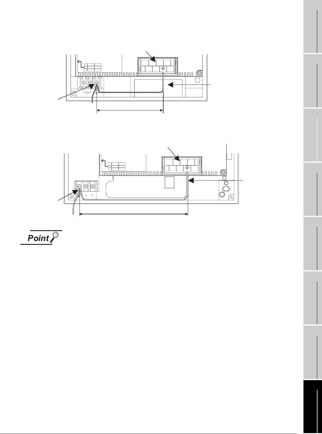
(a) When connecting CC-Link, use the grounding wire of the FG1 terminal on the CC-Link
communication module to connect to the FG terminal of the GOT power section.
Use a grounding wire of 300 mm or less.
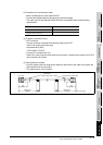
Use a CE compatible product for 24 V DC external common power source for GOT.
The EMC test run by our company was confirmed with the same panel components as
the DENSEI-LAMBDA type JWS 50-24 or DLP120-24-1 installed.
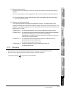
DA
1357
2468
DG NC NC
DB SLD (FG1) NC
BD999C127H01
SW
1
2
ON
HOLD
4
OFF
CLEAR
1
CC-Link communication module terminal block
GOT FG
terminal
Ground wire
(Within 300mm (11.81 inch))
<For A95*GOT>
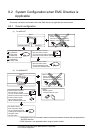
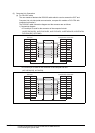
CC-Link communication module terminal block
GOT FG
terminal
Ground wire
DA
1357
2468
DG NC NC
DB SLD (FG1) NC
BD999C127H01
SW
1
2
ON
HOLD
4
OFF
CLEAR
1
0V 24V
INPUT
<For A956WGOT>
(Within 300mm (11.81 inch))