


6 - 12
6.1 GOT Main Unit
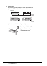
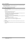
6.1.4 Installation of handy type GOT
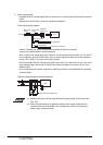
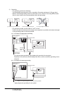
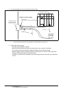
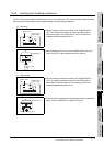
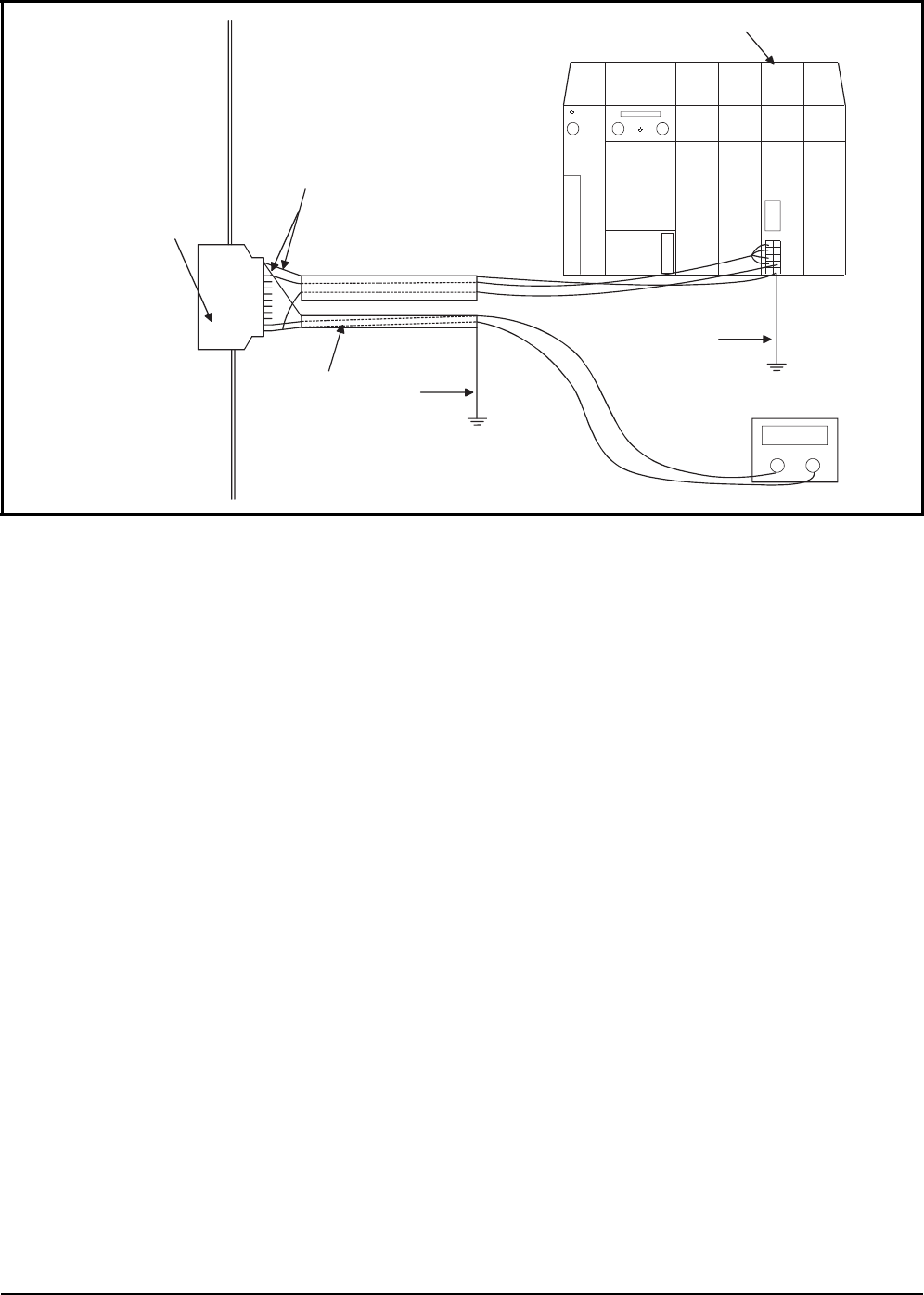
2) An internal diagram of the control panel is shown below.
*1: Separately ground the power wire and signal wire.
*2: Power wire and the signal wire must separated by a separate shield and ground to FG.
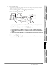
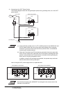
3) Notes when cable is made.
• The cable must be 200m or shorter.
• When branching inside and outside the control panel, use a connector in between.
The connector used must be able to attach the earthing to the connector casing.
• When the cable is made, the terminal 24VDC of the connector on the GOT side is connected
with the 24VDC power supply of the control board.
Therefore, it should not be connected to the power supply terminal in the back of the main body
of GOT.
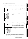
Connector which can
ground earth line to
casing of connector
*1 *2
Inside control panel
Ground wires
(Ground to the connector's metal section.)
Computer link module
24VDC wire
12/24VDCpowe
r
FG wire
FG wire