


6.1 GOT Main Unit
6.1.4 Installation of handy type GOT
6 - 11
1
OVERVIEW
2
SYSTEM
CONFIGURATION
3
PERFORMANCE
4
NAMES OF
THE PARTS AND
THEIR SETTINGS
5
ROUGH
PRE-OPERATION
PROCEDURE
6
HANDLING
7
MAINTENANCE AND
INSPECTION
8
EMC DIRECTIVE
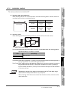
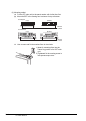
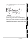
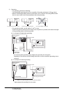
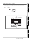
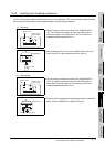
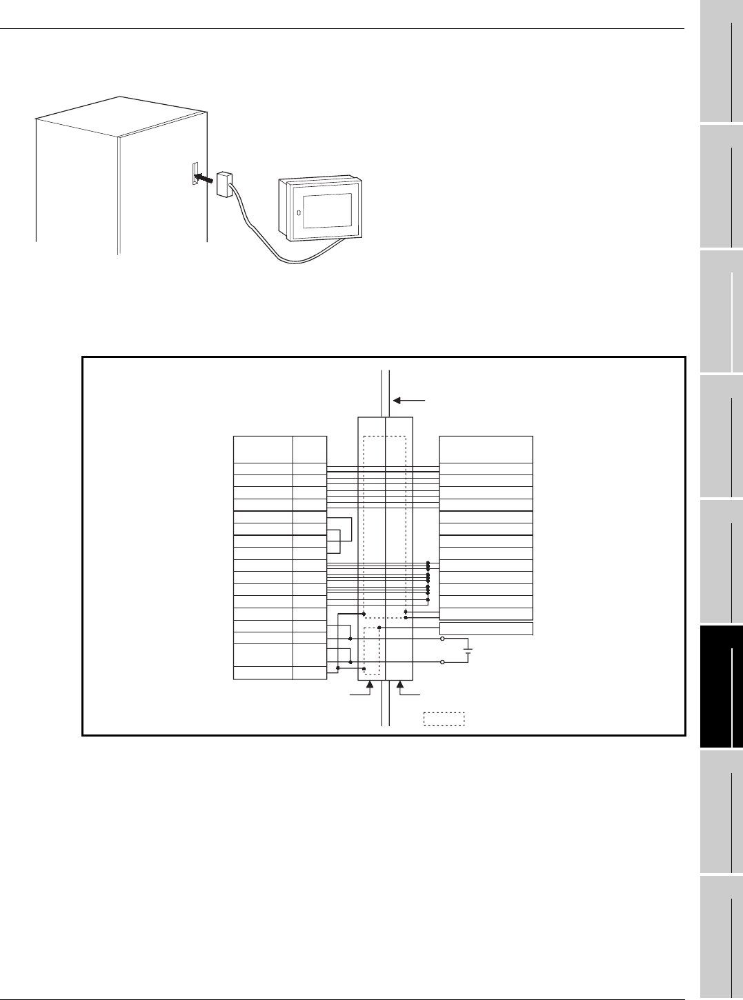
6.1.4 Installation of handy type GOT
The A950GOT can be used as a handy type, in addition to the conventional installation method.
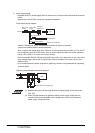
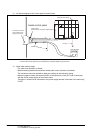
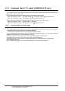
RS-422 cable to connect the GOT and the computer link unit must be prepared by the user.
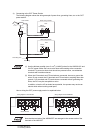
1) Wiring diagram
RS-422 cable
Control cabinet
A950GOT
18
RDA
RSB
SG
2
15
3
16
5
4
17
7
8
21
20
GOT side
(17JE-23250-02)
Signal
Pin
No.
Signal
Computer link module side
RDB
SDA
SDB
RSA
CSA
SG
CSB
SDA
SDB
SG
FG
Shield
RDA
RDB
24VDC
24VDC
24GDC
10
11
22
23
12/24VDC
Metal case
FG
Control panel door, etc.
(Inside control panel)
Connector (13JE-13250-02, etc.) Connector (13JE-23250-02, etc.)
24GDC