


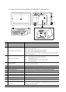

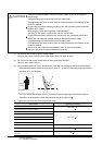
6.1 GOT Main Unit
6.1.2 Installation method
6 - 3
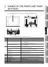
1
OVERVIEW
2
SYSTEM
CONFIGURATION
3
PERFORMANCE
4
NAMES OF
THE PARTS AND
THEIR SETTINGS
5
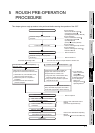
ROUGH
PRE-OPERATION
PROCEDURE
6
HANDLING
7
MAINTENANCE AND
INSPECTION
8
EMC DIRECTIVE
6.1.2 Installation method
This section provides how to install the GOT.
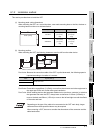
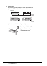
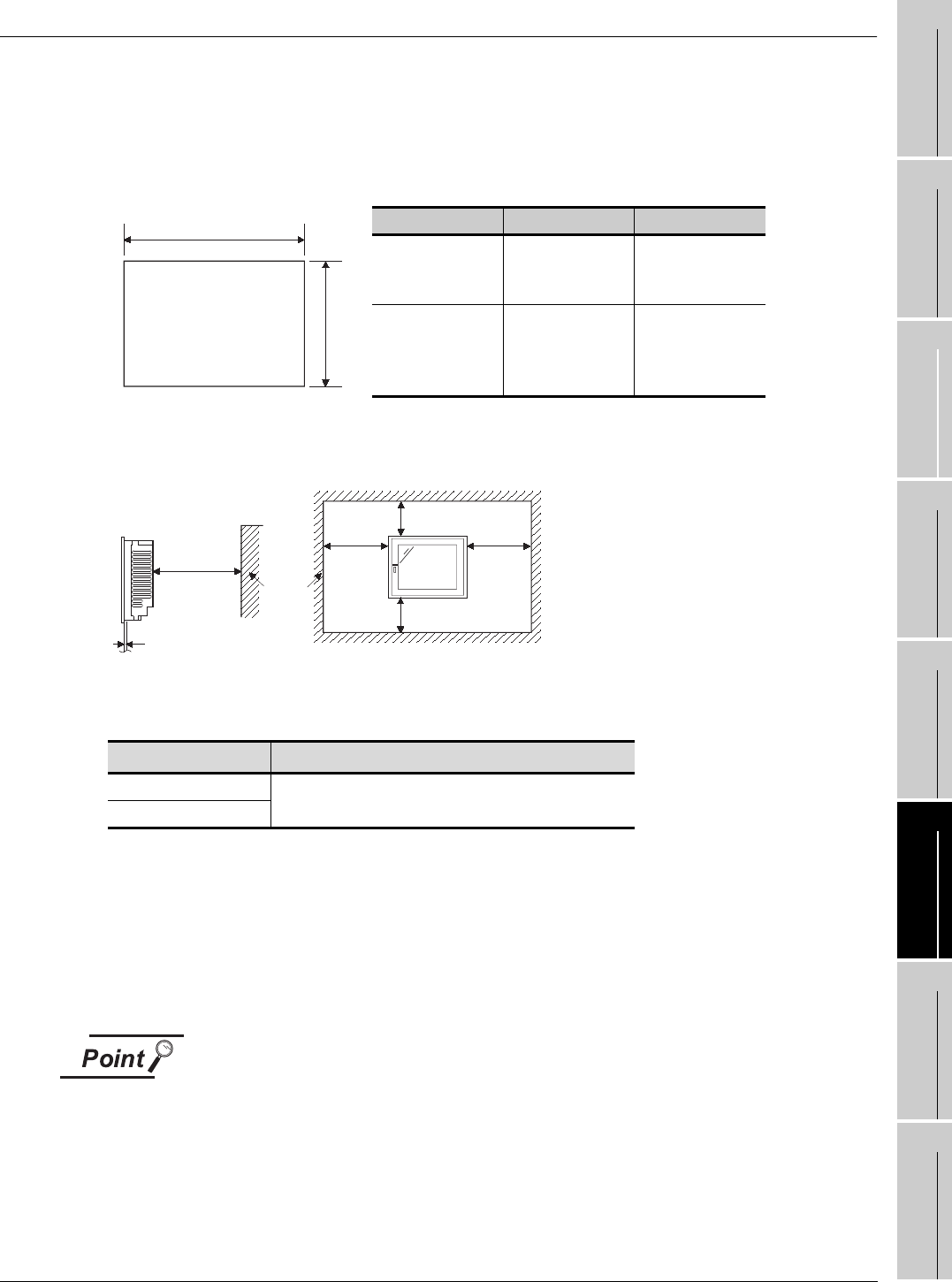
(1) Mounting panel cutting dimensions
When mounting the GOT on a control box door, user-made mounting base or the like, the door or
mounting base must be cut as indicated below.
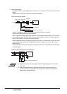
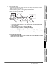
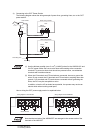
(2) Mounting position
When mounting the GOT, the following clearances must be left from the other device.
Part A size: Because the connection cable of the GOT is pulled downward, the following space is
required according to its radius of curvature.
Part B size: Please allow a gap 80mm (3.15inch) or more from the structure and other equipment in
the upper part of the unit to often allow good ventilation.
Part C size: When installing devices that generate radiated noise (such as a contactor) or a device
that generate heat near the GOT, always leave a clearance of 100mm (3.94inch) or
more to the back and 50mm (1.97inch) or more to the left and right to avoid the effects
of the noise and heat.
Depending on the type of the cable to be connected to the GOT main body, longer
clearances than those specified above may be required.
When mounting a GOT, be sure to consider the dimensions of the connector and the
cable bend radius.
Type A [mm](inch) B [mm](inch)
A95*GOT
156 (6.14)
[+1.0 (0.04),
-0(0)]
123.5 (4.86)
[+1.0 (0.04),
-0(0)]
A956WGOT
205.5 (8.09)
[+1.0 (0.04),
-0(0)]
123.5 (4.86)
[+1.0 (0.04),
-0(0)]
Item A [mm (inch)]
A95GOT
130 (5.12) or more
A956WGOT
Panel opening
A
B
Plate thickness
within 2 to 4mm (0.08 to 0.16inch)
C
Other
device
B
50mm
(1.97inch)
or more
50mm
(1.97inch)
or more
A