


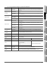
2.1 Overall Configuration
2 - 1
1
OVERVIEW
2
SYSTEM
CONFIGURATION
3
PERFORMANCE
4
NAMES OF
THE PARTS AND
THEIR SETTINGS
5
ROUGH
PRE-OPERATION
PROCEDURE
6
HANDLING
7
MAINTENANCE AND
INSPECTION
8
EMC DIRECTIVE
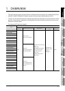
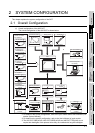
2 SYSTEM CONFIGURATION
This chapter explains the system configuration of the GOT.
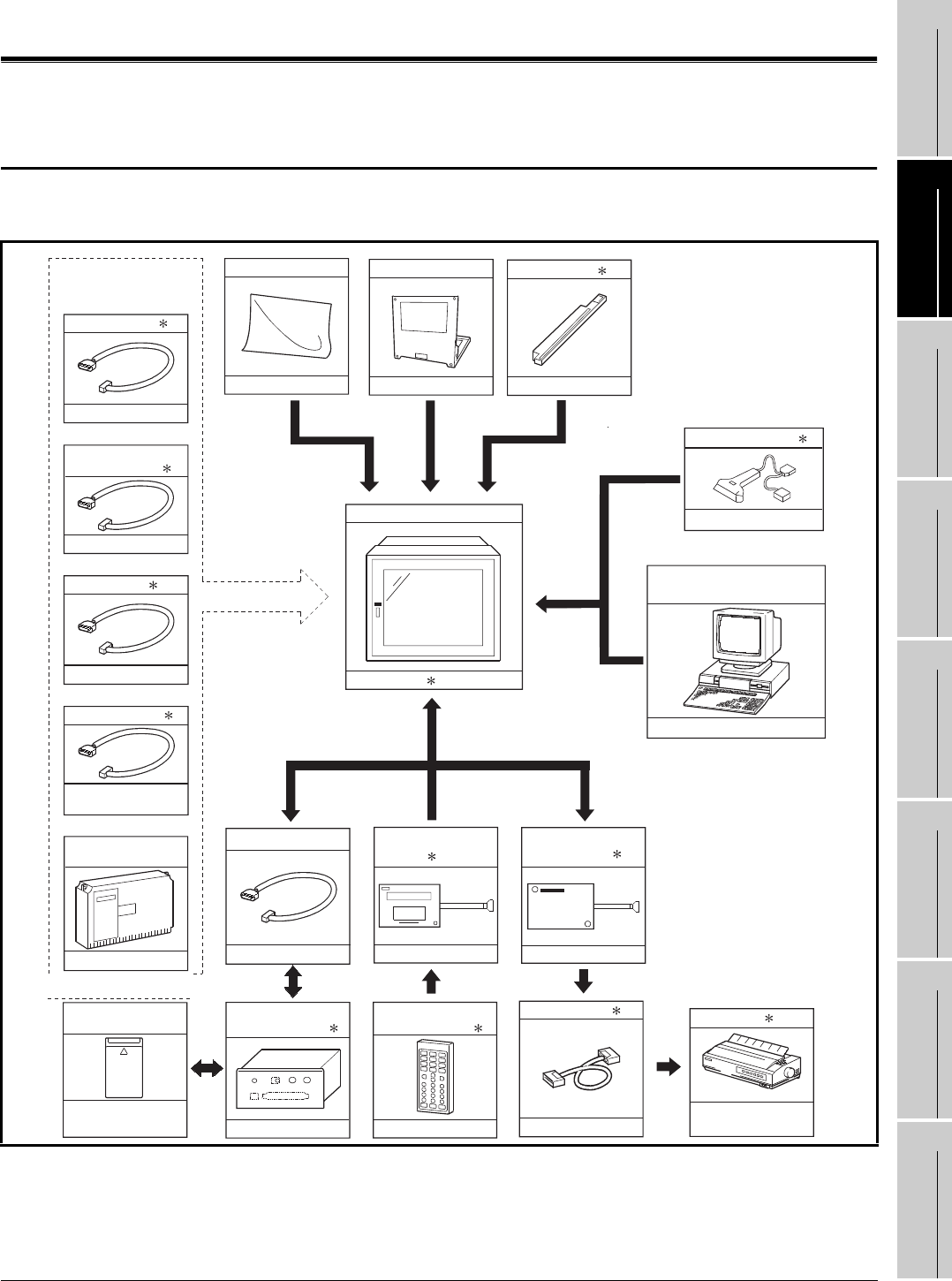
2.1 Overall Configuration
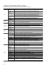
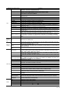
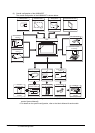
(1) Overall configuration of the A95*GOT
The overall configuration of the A95*GOT is shown below.
*1 For details of the system configuration, refer to the [GOT-A900 Series User's Manual (Con-
nection System Manual)].
*2 For details on the system configuration, refer to the User's Manual of each module.
*3 The A95*GOT-SBD(-M3)-B, A95*GOT-QSBD(-M3)-B and A95*GOT-TBD(-M3) do not
require their backlights to be replaced since they are installed with long-life backlights.
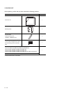
Backlight
A9GT-50LT
Protective sheet
A9GT-50PSC
Debug stand
A9GT-50STAND
Printer interface
module
A9GT-50PRF
Commercially available
Commercially available
External I/O module
A8GT-50KBF
e.g. A8GT-TK
Memory card cable
A85GT-C05H
A1SD59J-MIF
e.g. AC30PI0-20P
PC card
(Memory card)
Commercially
available
Numeric key panel
Communication
module
e.g. A9GT-Q71LP23
For A956GOT
e.g. A30R4-25P
For A950GOT
RS-422 cable 1
e.g. A8GT-C12NB
For A951GOT
Bus cable 1
Fabricated by
the user
For A953GOT
RS-232C cable 1
Bar Code Reader 1
Personal computer
for drawing
2
1
Memory card
interface module
2
2
Printer cable 1
Printer 1
Communication cable/
module connected
(e.g. key board)
e.g. A9GT-QC150BS
For A951GOT-Q
Bus cable for
QCPU(Q mode) 1
GOT
A95 GOT
3
Commercially
available