


7
6 -
5/8
"
16.83cm
17-
1/16
"
43.34cm
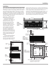
Cutout Opening for Custom Mounting
C2200
Front Panel
Custom Cabinet
Cutout
Cutout
Opening
for
Ventilation
Cutout Opening for Ventilation
Support
Shelf
Cabinet
Front
Panel
Chassis
Spacers
C2200
Side View in a
Partially Open
Custom Cabinet
C2200
Support Shelf in
Custom Cabinet
6-
1/2
"
16.51cm
12"
30.48cm
13-
1/4
"
33.66cm
2"
5.08cm
10-
1/2
"
26.67cm
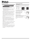
Notes: Center the Cutout Horitzonally on unit.
For purposes of clarity, the above
illustration is not drawn to scale.
Opening for
Ventilation
5-
3/4
"
14.61cm
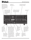
Cutout Opening for Ventilation
Chassis
Spacers
C2200
Side View
in Enclosed
Custom Cabinet
Cutout Opening for Ventilation
Other Component
in Enclosed
Custom Cabinet
Cool Air
Input
Warm Air
Output
Ventilaton Fan
Ventilaton Fan
Enclosed Custom Cabinet
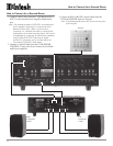
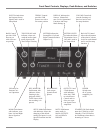
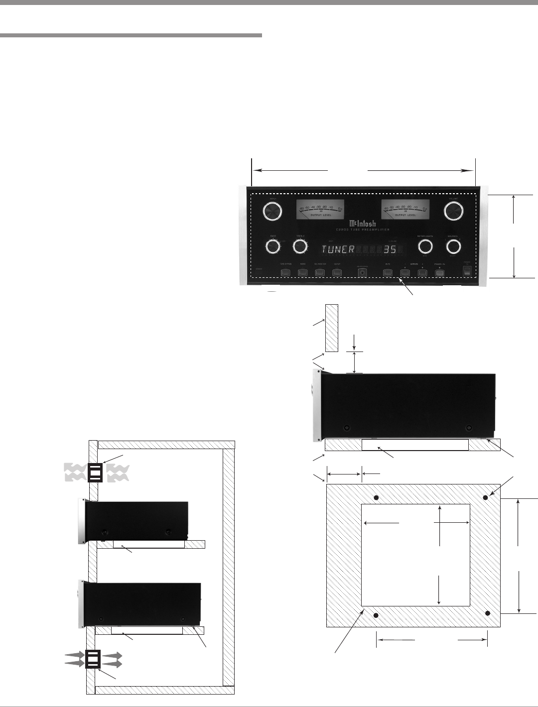
Installation
The C2200 can be placed upright on a table or shelf, stand-
ing on its four feet. It also can be custom installed in a piece
of furniture or cabinet of your choice. The four feet may be
removed from the bottom of the C2200 when it is custom
installed as outlined below. The four feet together with the
mounting screws should be retained for possible future use
if the C2200 is removed from the custom installation and
used free standing. The required
panel cutout, ventilation cutout
and unit dimensions are shown.
Always provide adequate
ventilation for your C2200. Cool
operation ensures the longest
possible operating life for any
electronic instrument. Do not
install the C2200 directly above
a heat generating component
such as a high powered ampli-
fier. If all the components are
installed in a single cabinet, a
quiet running ventilation fan can
be a definite asset in maintaining
all the system components at the
coolest possible operating tem-
perature.
A custom cabinet installation
should provide the following
minimum spacing dimensions for
cool operation. Allow at least 2
Installation
inches (5.08cm) above the top, 2 inches (5.08cm) below the
bottom and 1 inch (2.54cm) on each side of the A/V Control
Center, so that airflow is not obstructed. Allow 19-1/2
inches (49.53cm) depth behind the front panel. Allow 1-1/8
inch (2.9cm) in front of the mounting panel for knob clear-
ance. Be sure to cut out a ventilation hole in the mounting
shelf according to the dimensions in the drawing.