25
Technical Description
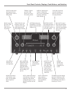
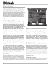
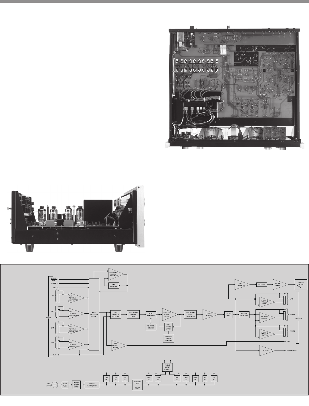
Side Inside View of the C2200
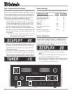
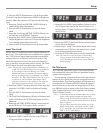
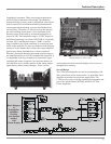
Bottom Inside View of the C2200
Logarithmic Attenuator. There are stringent requirements
for the Volume Attenuator in this design. The channel to
channel tracking accuracy must be maintained. After a great
deal of research we found that mechanical potentiometers
cannot approach the tracking accuracy that McIntosh felt
was necessary. Therefore, we choose to use a dual attenua-
tor with switching driven from a 16-bit serial data word.
Resistor values are decoded by an internal multiplexer to
steps of 0.5dB. Total attenuator range is 107dB. Step error
and channel matching is less than .1dB. THD+N is typically
less than .001% and dynamic range is 120dB. A second
stage is added to the volume attenuator. It controls the gain
of the output amplifier. Its steps are interlaced with the main
section in such a manner that it reduces the output amplifier
gain to unity almost immediately as volume is reduced.
Therefore, noise and distortion generated in earlier stages is
not amplified and low level S/N is dramatically improved. It
is comparable to having a straight wire between the input
switching and output connector. Care has been taken to in-
sure that there are no audible artifacts in the analog output
signal during volume control changes. There is a zero
crossing detector built in and all changes in level occur at
the signal zero crossing.
Overall Design
The C2200 was designed to use the best components avail-
able. All resistors are the lowest noise 1% metal film. Each
amplifier section has its own power supply filter. The
C2200 is truly worthy of being considered a companion and
peer of the world famous MC2000 and MC2102 Tube
Power Amplifiers.
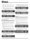
Block Diagram
of
Preamplifier
and Meter
Circuitry
(one channel
shown)
with
Power Supply


