


4
Important Information
1. The C2200 uses Vacuum Tubes for amplifying the audio
signal. The C2200 is designed to have only qualified
Service Personnel perform any part(s) replacement
including all the vacuum tubes.
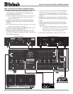
2. For additional information on Audio Connections, refer to
the Owner’s Manual(s) for the component(s).
3. Connecting Cables and Connectors are available from the
McIntosh Parts Department:
Data and Power Control Cable Part No. 170-202
Six foot, shielded 2 conductor, with 1/8 inch stereo mini
phone plug on each end.
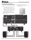
4. The Main AC Power going to the C2200 and any other
McIntosh Component(s) should not be applied until all the
system components are connected together. When the
C2200 and other McIntosh Components are in their
Standby Power Off Mode, the Microprocessor’s Circuitry
inside each component is active and communication is
occurring between them. Failure to do so could result in
malfunctioning of some or all of the system’s normal
operations.
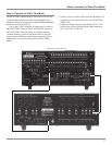
5. Up to four Sensors can be wired in parallel for Remote
Control of the C2200 from other rooms.
6. Balanced and Unbalanced Inputs and Outputs can be
mixed. For example, you may connect signal sources to
Unbalanced Inputs and send signals from the Balanced
Outputs. You can also use Balanced and Unbalanced
Outputs simultaneously, connected to different Power
Amplifiers.
7. A McIntosh Power Controller may be added to the C2200 to
provide AC Power Switching to components that do not
have Power Control Connections. See your McIntosh
Dealer for additional information.
8. Sound Intensity is measured in units called Decibels and
“dB” is the abbreviation.
9. The PHONO Circuitry uses four Vacuum Tubes. Those tubes
are only Powered-On (glow coming from the tubes) when
the AUX Input is re-titled to PHONO in the Setup Mode.
Refer to page 15 “Re-Titled Inputs” for additional
information.
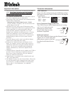
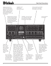
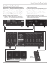
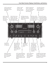
XLR Connectors
Below is the Pin configuration for the XLR Balanced Input
and Output Connectors on the C2200. Refer to the diagram
for connection:
PIN 1: Shield/Ground
PIN 2: + Input
PIN 3: - Input
Power Control and Trigger Connectors
The C2200’s Power Control Outputs provide a 5 volt sig-
nal. Use a 1/8 inch stereo mini
phone plug to connect to the
Power Control Input on other
McIntosh Components.
Data Port Connector
The C2200’s Data Port Output provides Remote Control
Signals. Use a 1/8 inch stereo mini
phone plug to connect to the Data
Port Inputs on McIntosh Source
Units.
Connector Information
Positive
N/C
Ground
Pin 1
Pin 2
Pin 3
Data Signal
N/C
Ground