24
McIntosh Laboratory, the company who introduced the
world’s first amplifier that could be called “High Fidelity”,
has done it again. The McIntosh engineering staff has cre-
ated a Tube Preamplifier without compromise, using the
most advanced McIntosh circuit design concepts. Creating a
Preamplifier with this level of performance did not come
easily. Many months of design, testing and measuring were
required. Extensive controlled listening tests, the ultimate
form of measuring, were made before the final design was
accepted.
Input and Output Switching
All signal switching in the C2200 is done by Electro-Mag-
netic devices. Electro-Magnetic Switching is a proven tech-
nology that uses the latest in materials and manufacturing
methods. Each switch consists of a glass tube that is filled
with an inert oxygen-free atmosphere and sealed with tiny
leads protruding from either end. These leads extend into the
tube and overlap one another with a separation of a few
thousandths of an inch. The leads are made from a ferrous
material that is influenced by a magnetic field. They are
first plated with gold as a base material, then with rhodium
and finally ruthenium. Ruthenium is the best contact mate-
rial known.
The glass assembly is then placed in the center of a mul-
tilayer coil of copper wire. The entire assembly is molded
together in a tough shock absorbing material. The switch
and coil connectors extend from the bottom in the form of
printed circuit board terminals. When a DC voltage is ap-
plied to the coil, current flows and creates a magnetic field.
The force of the field causes the leads to bend and contact
one another inside the sealed glass tube. The inert gas elimi-
nates corrosion of the contacts and insures a low resistance,
distortion free switch.
All inputs, outputs, and data ports are controlled by
logic circuits in the C2200. The logic is changed by Front
Panel Push-buttons or by a microprocessor IR decoder. This
microprocessor IR decoder is programmed with exclusive
McIntosh software. It receives data from the Front Panel or
Keypad/Sensors and provides the command signals for in-
put switching, data switching, and volume control.
Phono Circuitry
The PHONO amplifier uses 12AX7 tubes. Its input stage
has been optimized for low noise and low distortion perfor-
mance. Open loop gain of this circuit is 10,000. With high
open loop gain, a large amount of negative feedback can be
used around the phono amplifier to further reduce noise and
Technical Description
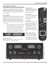
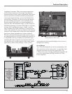
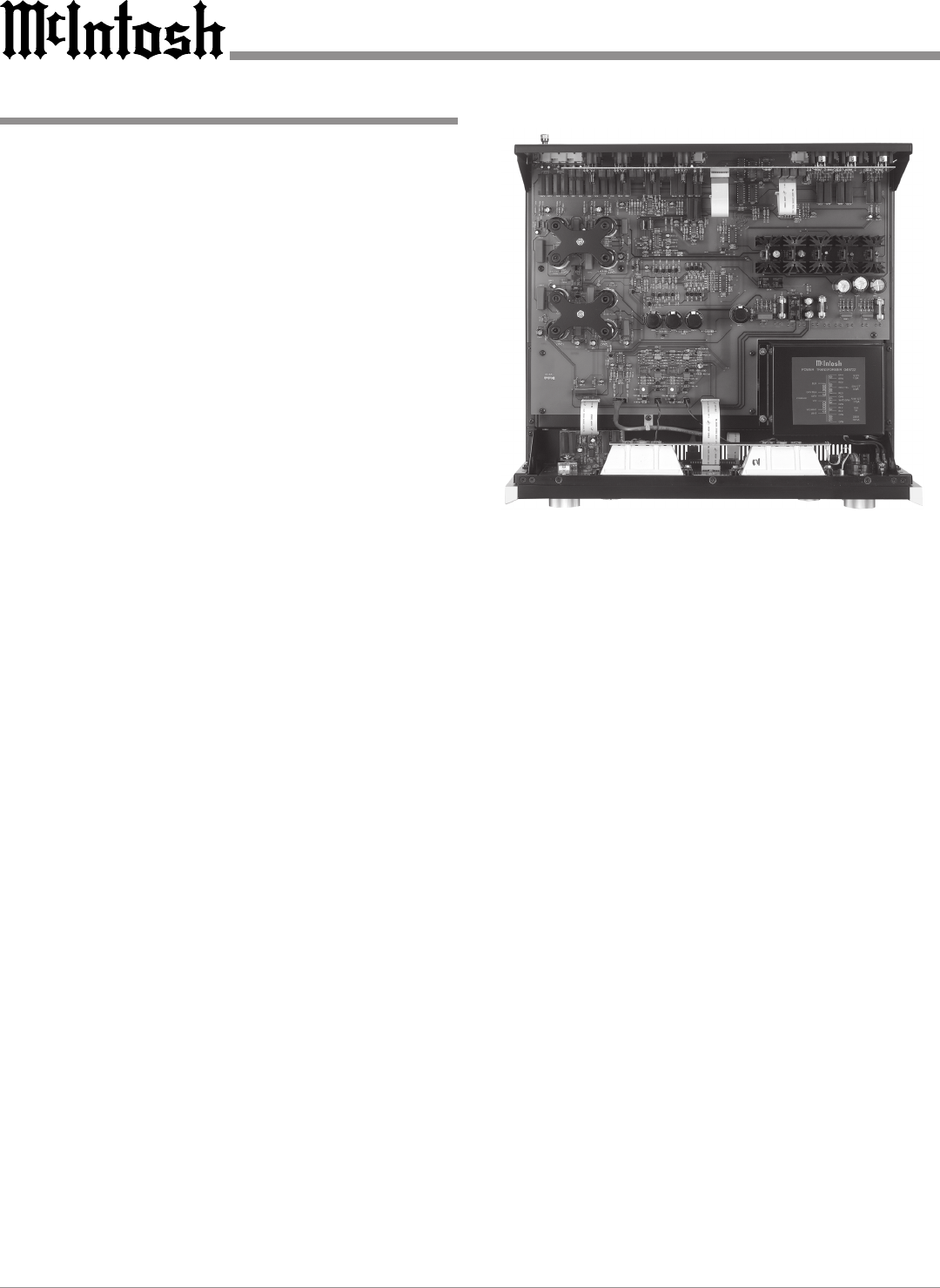
Top Inside View of the C2200
distortion. The feedback network also provides precision
RIAA frequency compensation.
Input sensitivity of the phono amplifier is 4.4 millivolts.
The gain of the amplifier is 40dB at 1000Hz. The phono
amplifier has a very wide dynamic range. At 1000Hz, the
phono input circuit will accept 50 millivolts without over-
load, a voltage far greater than the output of any current
magnetic phono cartridge. Therefore, phono input overload
is virtually impossible. A signal level of 10 millivolts at the
phono input at 1000Hz will produce 1 volt at the TAPE out-
put. This output has a source impedance of 500 ohms un-
balanced.
Tone Control Circuitry
The TONE control section uses 12AX7 amplifiers. The am-
plifier stages have been optimized for low noise and mini-
mum distortion. Other electrical circuits are arranged in a
configuration that is the equivalent of a series turned circuit.
A control potentiometer inserts this series tuned circuit into
either the feedback or input section of the tone amplifier.
This provides a 12dB boost or cut at the frequency of the
tuned circuit. The overall gain of the stage is 0dB when the
potentiometer is at its center detent position. A TONE BY-
PASS Switch is provided to remove all tone control circuits
from the signal path.
Volume Control Circuitry
The VOLUME Control for the C2200 is a very special “Hi
Tech” circuit. It employs a Microprocessor Controlled


