


Connecting the KPS 25s
to Your System
WARNING
When making connections to this compo-
nent or any other, make sure the power
amplifier is Off. Make sure all cable termi-
nations are of the highest quality, free from
frayed ends, shorts, or cold solder joints.
1. Connect the outputs of associated
source equipment to the inputs of the
KPS 25s.
2. Connect the left and right outputs of the
KPS 25s to the appropriate associated
equipment.
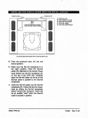
3.
When connecting the KPS 25s to AC
power, first connect the EIC Standard
15 amp AC power cord between
the KPS-25s and the wall socket. Then
switch the power on from the Rear
Panel Power Switch. The word KRELL
will momentarily appear in the Menu
Display Window located on the dght
front panel of the KPS 25s. This indi-
cates that the KPS 25s has initialized
and is ready for operation. The unit is in
Stand-by mode.
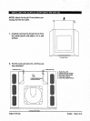
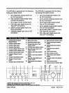
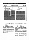
THE KPS 25s BACK PANEL
1 Left and right balanced Inputs 11
2 Inputs from tape deck
3 Outputs to tape deck
12
4 Single-ended input 1
5 SinglHnded Input 2
6 Single-ended input 3
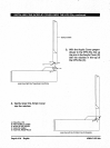
7 Acrylic Cover damper adjust-
ment corrtrol
8 Rxed level balanced outputs
9 Variable level balanced
outputs
10
13
14
15
Fixed level single-ended
16
outputs
Variable level single-ended 17
outputs
KrelP CAST
TM
outputs (vari- 18
able level outputs for use with
other KrelP CAST
TM
equipped
19
components)
20
BAJ fiber optic digital outputs
(via TosLink
TM
connectors)
21
SPDIF co-axial digital outputs
(via RCA connectors)
22
AES/EBU digital output (via an
XLR connector)
23
BAJ fiber optic digital inputs
(via TosLink
TM
connectors)
24
25
SPDIF co-axial digital Inputs
(via RCA connectors)
AES/EBU digital input (via an
XLR connector)
Main on/off power switch
Fuse holder
IEC Standard 15 amp AC
power cord receptacle
KrelP RemoteLink
TM
commu-
nications output data pert
KrelP RemotaLlnk
TM
commu-
nicatlons input data port
RC-5 baseband Input
12 Volt trigger output
1 2
3 7
1 4 5 6 10
8
11
Page 8 of 20 English
KRELL
®
KPS 25s