


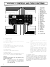

With the RIT switch ON, the RIT knob allows the Operator
to vary the receive frequency by about
f
1.5 kHz without
affecting the transmit frequency. The Center Position “0”
is RIT-OFF.
26 RIT Control 36 M.
S
Switch
This switch selects and scans the frequency stored in the
memory channel.
Scan
is released by the HOLD switch or
by setting the transceiver in transmit mode.
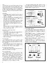
27
IF
SHIFT Knob
By using this control, the IF crystal filter Center frequency
can be shifted + 1 kHz, allowing adjustment of tone quali-
ty, or eliminating interference from adjacent frequencies.
For normal Operation, this control should be set to the
Center “0” Position (detent).
28 SQUELCH Control
Turning this control clockwise during FM mode will
activate the squelch circuit.
29 SCAN-W
This switch is used to select the
scan
width (0.5, 1, 3, 5
and 10 MHz).
30 AF GAIN Control
This control adjusts the gain of the receiver audio amplifier.
Clockwise rotation will increase the output
level
31 RF GAIN Control
For adjusting the RF amplifier gain of the receiver. The gain
is minimum at the extreme counterclockwise Position. Nor-
mally, this control is set in its extreme clockwise Position.
32 F. STEP Switch
By using this switch, the VFO frequency is varied at a slow
or fast
Speed
as shown below. The operating conditions
can be checked on the F. STEP indicator.
F. STEP
OFF ON
SSB.CW,FM
20 Hz 200 Hz
FM
-
CH
12.5 kHz 5 kHz
1
33 RIT Switch
This push switch turns the RIT (Receiver Increment Tuning)
circuit ON and OFF. With the switch depressed, the circuit
is activated and the RIT indicator is illuminated. The RIT cir-
cuit is turned OFF when the switch is out.
34 SCAN Switch
This switch turns ON and OFF the VFO
scan
circuit. The
VFO frequency is scanned at the
Speed
selected by the
F. STEP switch. The switch is also used for re-scanning of
M. S (memory scan) or for scanning at busy stop.
35 HOLD
This switch is used to stop
scan
Operation.
37 BAND Switch
For selecting the band
(144-145
MHz or
430-439
MHz)
to be operated. By pressing the UP switch, the frequency is
stepped up band by band. When the DOWN switch is
pressed, the frequency is stepped down band by band. In
either case, the band is switched in 1 MHz Steps.
38 M (Memory) Switch
This switch is used to store the desired frequency in the
memory channel.
When the switch is depressed, an oscillation Sound is
heard, indicating that the frequency is stored in the
memory channel.
39 F. LOCK Switch
This switch
locks
the operating frequency of VFO. With the
switch ON, the VFO frequency remains unchanged even
when the tuning knob, BAND switch or MIC UP/DOWN
switch is manipulated. This feature is useful when
operating the transceiver on the same frequency for many
hours, or when it is used for mobile Operation.
The RIT switch can be used even in the ON Position of the
F. LOCK switch. The F. LOCK indicator will light when the
F. LOCK switch is ON.
40 M.
R
(Memory Recalll Switch
Memory channel is called out when this switch is turned
ON. For the channels in which frequencies are not stored,
the corresponding channel numbers are indicated.
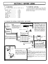
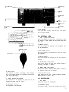
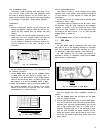
3-2. REAR PANEL
1
430 MHz ANT (antenna) Connector IN type)
For connection of the 430 MHz band antenna.
2 144 MHz ANT (antenna) Connector (M type)
For connection of the 144 MHz band antenna.
3 Heat Sink
Dissipates heat from the final Stage transistors and power
supply transistors.
4 CW KEY Jack
This
jack
is used for operating the transceiver in CW mode.
Connect a telegraph key using a 2P plug.
5 SP (Extemal Speaker) Jack
Connect an external speaker of 4-8 ohms impedance using
the supplied plug.
7