


4-
1. ANTENNA
The Performance of the transceiver depends upon the
type of antenna to be used. To ensure the maximum perfor-
mance of the TS-780, select a suitable antenna and adjust
it for the best condition.
Common Antenna for
144/430
MHz Operation
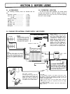
The TS-780 is designed so that two different transmit
Outputs (144 and 430 MHz) are supplied to individual
antennas. Use of individual antennas is recommanded as it
simplifies the antenna matching and minimizes the loss
cuased by antenna. However, if it is desired to use a com-
mon antenna, available from market, because of installa-
tion conditions, etc.,
it should be properly adjusted and
connected by carefully following the instruction manual
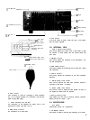
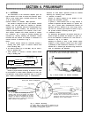
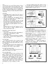
furnished with the antenna. An example of connection of a
common antenna is illustrated in Fig. 4.
Notes:
1. A common antenna should be connected through a
dividing filter (some types of common antenna have
built-in dividing filter).
2. An antenna selector (up to 430 MHz) may be used in
lieu of a dividing filter.
3. Never attempt to connect a common antenna without
using a dividing filter.
144 MHz cable
TS-780
Dividing filter
Antenna
430 MHz cable
L
cable
Fig. 4 Connection of Common Antenna
I
Type of Antenna
Choose a proper antenna according to whether it is used
for fixed Station or mobile Station Operation. For fixed sta-
tion Operation, a Yagi antenna (directional type) or a ground
plane antenna (omnidirectional type) is recommended.
Antennas for fixed Station Operation should be installed
observing the following three conditions:
l Selection of Antenna
Choose an antenna suitable for the purpose of use,
budget and installation location.
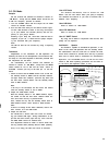
In general, a beam antenna such as Yagi antenna is
suitable for Operation with DX stations or a specific sta-
tion, and a ground plane omnidirectional antenna for
Operation with
local
stations. In the case of Yagi anten-
nas, use of a stacked type antenna as shown in Fig. 5
will provide excellent directivity and RF gain.
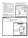
l Installation Location
used for satisfactory DX Operation.
The “A” Station
on
the
hill
provides better transceive opera-
tion than the
“B”
Station if the same type of antenna is used.
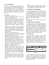
For satisfactory DX Operation, the antenna should be in-
stalled as high as possible. An example of a good
loca-
tion for the installation of antenna is on a hill such as
il-
lustrated in Fig. 6, “A” Station.
Installing as antenna in such a high location allows
reception of many stations; however, this often creates
a possibility of radio interference. Therefore, it is recom-
mended that a stacked type directional Yagi antenna be
Fig. 6 Good Location for Antenna Installation
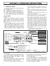
Ground plane antenna (omnidirectional)
Directivity of “E” Station
Directlon of
beam
.
*
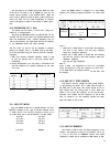
“A”
and “C” stations are transmitting with the same
frequency, while
“B”
and “D” stations are receiving
the Signal. In this case, radio interference is very little.
However, if “E” Station is transmitting with the Same
freauencv and “A” and “C” stations are receivinq the
In areas crowded
with
many stations. it is recom-
mended that
a
beam antenna be used. as it
eliminates interference when those stations are
transmltting with the Same frequencv.
Signal, interference will possibly occur.
Fig. 5 Antenna Directivity
(The
Pattern Shows an Ideal condition. In practice, this pat-
tern becomes complex because it is influenced by surroun-
ding buildings and geographical features.)