


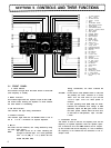
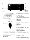

7 REV (Reverse) Switch
This switch is used to check repeater input
Signal.
By
depressing the switch, the TX and RX frequencies are
reversed. To reverse the frequencies once again, set the
transceiver in transmit mode while holding the switch in
the depressed Position.
8 TONE Switch
Tone oscillator switch which makes 1750 Hz FM wave
when pressed in FM mode only.
9 LOW POWER Switch
Set this switch to LOW Position and the FM transmit out-
put is reduced to about 1 Watt. Use the switch for FM
mode only. (This switch has no effect on SSB and CW
mode.)
10 NB (noise blanker) Switch
Use this switch during SSB or CW Operation to reduce
pulse ignition type noise from automobiles, etc. This is very
useful when receiving weak Signals.
(This switch will not function in FM mode.)
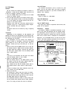
11 Meter switch
By using this switch, the meter functions as an
S
meter,
ALC meter or CEN (Center) meter.
Note: When the switch is set to the ALC/CEN Position
during FM transmission, the meter functions as an
RF meter but the meter pointer deflection will be
slightly deviated.
Meter functions
FM
SSB/CW
RX
TX
RX
TX
RF/S
S
RF
S
RF
I
ALC/CEN
I
CEN
/ OlZel /
’
/ ALC
I
12 VOX Switch
This switch is used for voice operated transmission on FM
or SSB, or semi-break-in Operation on CW (set to VOX posi-
tion). lt is also used in combination with the standby switch
or microphone PTT switch (set to MAN position).
13 Standby Switch
Set this switch to the down Position for reception, and to
the up Position for transmission. By pressing the
microphone PTT switch, the unit automatically shifts from
reception to transmission.
14 POWER Switch
The power to the unit is turned ON by setting the power
switch to the up Position, and turned OFF at the down
posi-
tion.
15 MIC Connector
Connector for microphone up/down input and PTT circuit.
16 PHONES Jack
This headphone
jack
allows use of a set of headphones of
8-l 6 ohms impedance. Connect KENWOOD headphones
HS-4, 5 or 6 available as an optional accessory.
A stereo headphones may also be connected.
17 MODE Switch
In FM-CH mode, the VFO frequency is switched in
20/10
kHz Steps.
In FM, LSB, USB or CW mode, the VFO frequency is swit-
ched in
20/200
Hz Steps.
18 PRIO. M Switch
Depress the PRIO. M
191
switch to
call
out the memory
channel 9CH. Depres the [IO] switch to
call
out the 1 OCH.
These memory channels are preset to 145.000.0 and
433.000.0, respectively, but can be set to any desired fre-
quencies.
19 TIGHT lever
This lever is used to increase the torque of the VFO dial
knob so that the knob can not be rotated by external shock.
20 F. STEP Indicator
This indicator will light when the F. STEP switch (32) is
ON.
21 Tuning Knob
Turn this knob to select
22 FUNCTION Switch
This function switch
your desired frequency.
selects one of the following
transceive functions. Normally
It
should be set to the
“A”
or “B” Position.
A-R: For VFO A Operation during reception and for VFO B
Operation during transmission.
A: For VFO A Operation.
8: For VFO B Operation.
8-R: For VFO B Operation during reception, and for VFO A
Operation during transmission.
23 MEMORY Selector
This switch selects any of the memory channels l-l OCH.
Use the switch when frequencies are stored in the memory
channels or the stored frequencies are called out in the ON
Position of the RM switch.
The channels
(9)
and
(
IO] are common to the priority chan-
nels [9] and [IO]. These channels are preset to
145.000.0 MHz and 433.000.0 MHz, respectively.
24 SSB MIC
This control adjusts the gain of the microphone amplifier
during SSB Operation. Adjust it so that the ALC meter does
not deflect beyond the ALC Zone.
25 RIT Indicator
This indicator will light when the RIT switch (33) is ON.
6