


IO.5 MHz1
When the scan, starting from 431.637.5 MHz, reaches
the upper limit 431.987.5 MHz, it jumps down to the
lower limit 431.500.0 MHz where the
scan
is started
again. This action is repeated while holding 0.5 MHz
width.
(1
MHz]
When the
scan
reaches from 431.637.5 MHz to the
upper limit 431.987.5 MHz, it jumps down to the lower
limit 431 .OOO.O MHz and reaches 431.987.5 MHz again.
This action is repeated while holding 1 MHz width.
[3
MHz]
Similarly, when the
scan
reaches
from the lower limit
431.000.0 MHz to the upper limit 431.637.5 MHz, it
jumps down to the lower limit and reaches the upper limit
again. This action is repeated while holding 3 MHz width.
The lower limit is 431.637.5 MHz minus the frequency
on 100 kHz
Order,
and the upper limit is 433.987.5 MHz,
one step lower than 434.000.0 MHz which is the lower
limit plus 3 MHz but the
scan
Starts from 431.637.5 MHz.
[5
MHz1
The upper and lower limits are calculated in the same
manner as for 3 MHz width. The
scan
is repeated between
the lower limit and the upper limit while holding 5 MHz
width.
[lO
MHz]
The
scan
is repeated between the upper limit
439.987.5 MHz and the lower limit 430.000.0 MHz
while holding 10 MHz width.
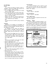
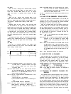
430 431
432
433 438 433
440
SCAN
.w
switch
I
I,
432.967.5
j-----
---------1
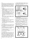
Note 1: In the SCAN W Position 3, 5 or 10, the
scan
in the
144 MHz band is repeated between the upper
limit 145.987.5 MHz and the lower limit
144.000.0 MHz.
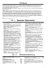
Note 2: In these Position, the
scan
does not shift over the
144 and 430 MHz bands. For example, when the
SCAN W is 5 in 438.250.0 MHz, the
scan
is ef-
fected holding 5 MHz width.
Note 3: The
scan
width should be calculated even in the
following
cases:
1)
When VFO (A,
B)
is switched.
2) When SCAN W switch is set to another posi-
tion.
3) When BAND switch is depressed.
Note 4: The
scan
width remains unchanged when the
SCAN switch is depressed for BUSY stop.
To Change the
scan
width, the
scan
should be
released.
Note 5: The BAND switch can be used during
scan
opera-
tion, but it does not function continuously when it
is kept depressed. This switch also functions even
when the F. LOCK switch is ON.
The
scan
is released when the PRIO. M, MR or MS switch is
set to ON.
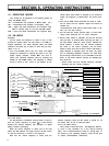
5-15 USE OF MS (MEMORY SCAN) SWITCH
When the 144 MS or 430 MS switch is set to ON, the
function (CH No.) flickers to indicate that the memory
channels (l-l 0 ch) can be scanned (the squelch threshold
should be set as in the case of VFO scan).
With the 144 MS switch ON, the memory channel for
144 MHz band can be scanned. With the 430 MS switch
ON, the memory channel for the 430 MHz band is scann-
ed. When both switches are ON, all the channels (both for
144 and 430 MHz bands) are scanned. To hold the scan,
use the procedure for VFO scan. To restart the scan, set
the SCAN switch to ON.
Note 1:
Scan
is not effected when the SCAN switch is
kept depressed.
Note 2: When
scan
is held in the ON Position of both MS
switches, it can be restarted by setting either
switch to OFF or by pressing the CALL or MR
switch.
Note 3: When all the channels are 144 MHz band and the
430 MS switch is set to ON, the function flickers
quickly and a oscillation Sound is heard con-
tinuously. This also occurs when all the channels
are 430 MHz band and the 144 MS switch is set
to ON.
Note 4: Only memorized channels are scanned.
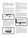
5-l 6 USE OF
PRIO.
M CHANNEL
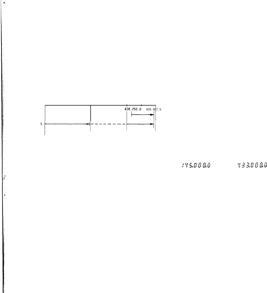
With the PRIO. M 9 or 10 switch set to ON, stored fre-
quencies in the memory channels 9 or 10 can be recalled
with first priority. In the channel 9 and 10.
145.000.0 MHz and 433.000.0 MHz are preset respec-
tively, while any frequency can be memorized in
each
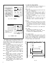
channel. Display of the PRIO. M channel is as follows:
c
:5;5,UfiQ,G
or c
$r_r(J,fia2,U
Note: 1 The PRIO. M 9 is
Prior
to the PRIO. M 10.
Note: 2 The PRIO. M channel frequency is displayed to
100 Hz digit.
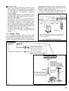
5-17 BACKUP OF MEMORY CHANNEL
FRE-
QUENCY
Any desired memory channel frequency can be stored in
the RAM (Random Access Memory) of the micro-
Computer. But the data (frequency) in the RAM is cleared
when the power switch is set to OFF. The transceiver has
its own built-in backup circuit to hold the data (frequency)
even when the power switch is OFF during both AC and DC
operations. By loading backup battery in the transceiver
battery case, the battery power is always supplied to the
backup circuit. In this way, the data is not. cleared
regardless of the Position of the power switch. The backup
18