


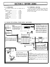

SECTION 1. FEATURES
1.
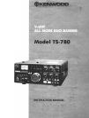
144/430
MHz, all mode (FM, SSB (USB, LSB), CW)
transceiver.
0 8 bit microprocessor controlled VFO and full variety of
auxiliary functions.
0 FM circuitry based on KENWOOD’s advanced
technology and outstanding SSB quality.
0 Buit-in VOX.
0 Buit-in side tone and CW circuitry capable of semi-
break-in Operation.
0 Adoption of power module in the transmitter final Stage
for dependable Operation on both bands.
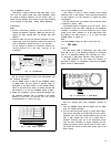
2. Built-in digital display that indicates operating frequency
in all modes.
0 Digital display equipped with easy-to-read green
Phosphor tubes.
0 7-digit digital display that directly reads down to
100 Hz.
0 Frequency indicator that reads out carrier positions
when mode of Operation is changed.
0 Two VFO’s (A and
BI
are built into the transmitter for
more enjoyable Operation such as “Cross-frequency”
Operation.
0 Buit-in 1 0-channel memory circuit stores operating fre-
quencies and bands. Two channels (CH9 and CH10)
can be called out by using CALL channel switch.
0 Easy-to-read display indicated 2 VFO’s
(
R,
b
),
memory
channels
(
1
-~8
)
and priority channels
(
c and c
)
0 Display function that clears frequency below 1 kHz in
FM-CH.
3. Dependable electrical and mechanical functions
0 VFO frequencies are switchable in 2 Speeds, SLOW (in
12.5 kHz, FM-CH) and FAST (in 5 kHz, FM-CH).
0 VFO knob equipped with variable torque mechanism.
0 Pushbutton band select switched (UP and DOWN) that
shift up and shift down frequency between 144 MHz
and 440 MHz in 12 bands at 1 MHz intervals.
0 Wide band design for both transmitter and receiver that
eliminates the need for tuning the RF circuits.
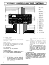
0 Panel layout based on human engineering.
0 Full variety of indicating functions to check operating
conditions (OFFSET, ON AIR, BUSY, F.LOCK, RIT,
F.STEP).
0 Amplified type AGC and ALC circuits that maintain
receive and transmit Outputs at constant
level
without
distortion.
4. A multitude of auxiliary functions for more enjoyable
Operation.
0 The use of RAM memory System enables any given fre-
quencies to be stored in or cleared. (IO memory chan-
nels).
0 Built-in back-up battery holder to keep data stored at all
times.
0 Built-in memory
scan
for selection between 144 MHz
and 430 MHz.
0 RIT circuit function on VFO, memory channels and
priority channels.
0 Adoption of frequency lock circuit.
0 A repeater shift circuit is provided, and the shift width
on the 144 MHz band is
-
600 kHz or + 600 kHz, and
that on the 430 MHz band is
-
7.6 MHz or
-
1.6 MHz,
which may be selected as required. The tone frequency
is 1,750 kHz. In the event of off band, the digital
display goes out and transmission is halted.
0 KENWOOD’s unique noise blanker (NB) circuit to
eliminate pulse type noise.
0 Four-function meter serves as S meter, RF meter, ALC
meter and Center meter.
0 RF power HIGH/LOW selecting function provides conve-
nience in transmission with
local
stations in FM.
0 Auxiliary (AUX) socket.
5. Designed for fixed and mobile Station Services.
0 ACIDC 2-way power Operation.
0 Equipped with a grip for carrying convenience.
0 Sufficient AF output power (2.5
W/4
9).
0 Built-in large sized speaker (7.5 cm). External speaker
connecting
jack.
3