


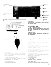
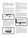
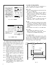

The VFO Knob is of variable torque type. When the lever
at the left of the knob is set to NORM, the knob can be
rotated quickly because of the flywheel effect. When the
lever is set to TIGHT, the knob is given a heavy torque and
hence the knob will not rotate accidentally by external
shock. This feature is useful for fine tuning or mobile opera-
tion.
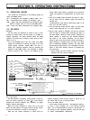
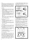
5-10 OPERATION OF 2
VFOs
The TS-780 has two VFO’s, A and B,
each
being con-
trolled by a microprocessor.
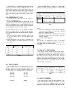
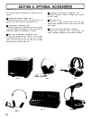
By using the FUNCTION switch, the desired VFO can be
selected. The use of two VFO’s also permits Operation with
their own frequencies
(Cross
channel Operation) such as
A-R or B-R Operation. The table below Shows the positions
of the FUNCTION switch and VFO’s selected.
The two VFO’s (A and
BI
can be operated in different
bands (for example, VFO A: 144 MHz, VFO B: 430 MHz;
or in the same band. They can also be used as a memory.
Examples:
1.
2.
With your contact’s schedule frequency stored in VFO
B, you can operate VFO A until your contact Starts
transmitting.
During FM Operation, you can locate a sub-channel and
shift the frequency for repeater Operation by the VFO
not in use.
FUNCTION
SWITCH
RECEPTION
TRANSMISSION
Table 2
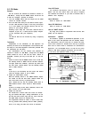
5-11 USE OF FM-CH
With the MODE switch set to FM-CH Position, the VFO
Operation changes to
click
type. In the OFF Position of the
F. STEP switch, the channel frequency shifts up in
12.5 kHz Steps, and in the ON Position, in 5 kHz Steps.
433.000 433.005
433.0125 433.010
433.0250 433.015
433.0375 433.020
433.9875
433.995
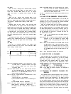
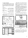
When the MODE switch is changed to or from FM-CH
Position, the operating frequency becomes as shown table
3.
Frequency
145.317.7
145.317.6 145.315.0 145.315
displayed
145.312.5
145.315
145.315.0
(NOTE: "1) (NOTE: '2)
Table 3
Note 1:
*
1
When the F. STEP switch is turned OFF, the frequency
will shift to the nearest 12.5 kHz step frequency
within the displayed frequency.
* 2 When the F. STEP switch is turned ON, the frequency
will shift the nearest 5 kHz step frequency within the
displayed frequency.
The 100 Hz digit disappears.
Note 2:
Table 3
Shows
the frequencies of VFO A. In the FM-CH
mode, the frequency of VFO B is shifted in the same way.
In the SSB mode, the frequency bellow
be changed.
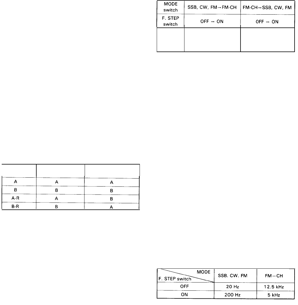
5-12 USE OF F. STEP SWITCH
10 kHz
Order
may
This switch is used to Change the step of VFO frequen-
cy. By pressing the switch, the F. STEP LED will light. In
the SSB, CW or FM mode, this switch should be set to
OFF, except when the tuning knob is used. When the
switch is set to ON, the frequency on the 100 Hz
Order
becomes even number and the frequency on the 10 kHz
Order
is cleared to “0”. The frequency remains the same
when the switch is set to OFF.
Table 4
5-13 USE OF MEMORY
This switch is used to store the desired frequency in the
memory. The frequency is stored in the channels
(1-1
0 ch)
by using the M switch and MEMORY selector. The stored
frequency is called out by pressing the MR switch to ON.
16