


VR-2Q90/VR-2OBC]/KRF-Vee81D/KRF-V7771OIEniK]
Connection of audio comoonents
................... iH IIIIIIIII IIIIIIIIIIII II I IIIIII Ill IIIIIII I IIIIqllllllll" I I IIIIIIIIrl IIII!1II _ !
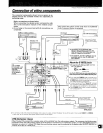
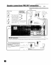
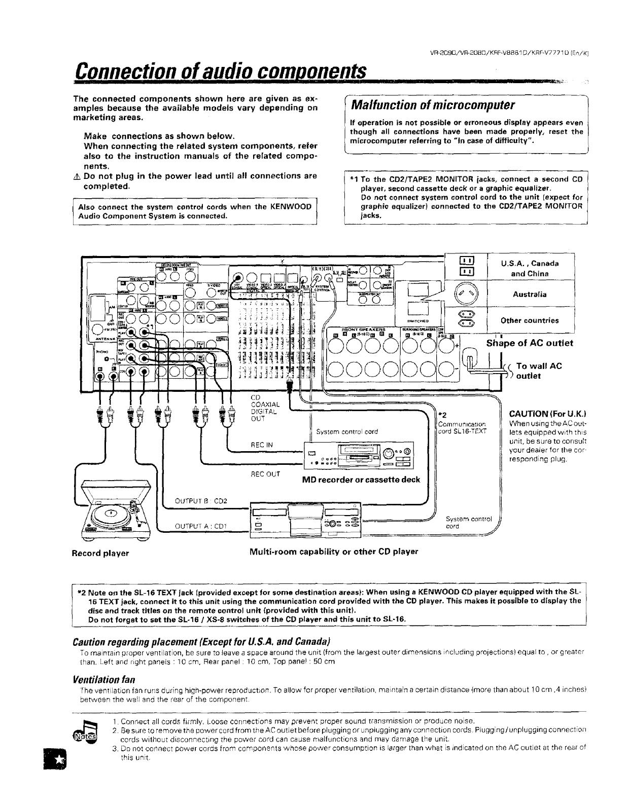
The connected components shown here are given as ex-
amples because the available models vary depending on
marketing areas.
Make connections as shown below.
When connecting the related system components, refer
also to the instruction manuals of the related compo-
nents.
Do not plug in the power lead until all connections are
completed.
Also connect the system control cords when the KENWOODAudio Component System is connected,
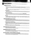
Malfunction ofmicrocomputer
If operation is not possible or erroneous display appears even
though all connections have been made properly, reset the
microcomputer referring to "in case of difficulty".
"1 To the CD2/TAPE2 MONITOR jacks° connect a second CD
player, second cassette deck or a graphic equalizer,
Do not connect system control cord to the unit Iexpect for
graphic equalizer) connected to the CD2/TAPE2 MONITOR
iacks.
U.S,A., Canada
and China
Australia
Other countries
I |
Shape of AC outlet
To wall AC
Record player
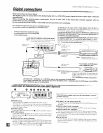
OUTPUT B CD2
,, OUTPUT A : CD1
CD
COAXIAL
DIGITAL
OUT
REC IN
REC OUT
System control cord
"'
! =o _ "_ i,==c:_:j{
MD recorder or cassette deck
*2
Corn mu_licatior;
cord SL 16-T_XT
System control
cord
/,
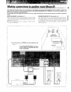
Multi-room capability or other CD player
CAUTION (For U.K.)
When using the AC out-
lets equipped with this
unit, be sure to consult
your deaJer for the cur
responding plug,
m
"2 Note on the SL-16 TEXT jack (provided except for some destination areas): When using a KENWOOD CD player equipped with the SL-
16 TEXT jack, connect it to this unit using the communication cord provided with the CD player, This makes it possible to display the
disc and track titles on the remote control unit (provided with this unit),
Do not forget to set the SL.16 / XS-8 switches of the CD player end this unit to SU16.
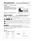
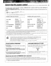
Cautionregarding placement (Exceptfor U.S.A. and Canada)
To maintain proper ventilation, be sure to _eave a space around the unit (from the largest outer dimensions including projections) equal to, or greater
than Left and right panels : 10 cm, Rear panel : 10 cm, Top pane! : 50 cm
Ventilationfan
The vent[ ation fan runs during high-power reproduction. TO allow for proper ventilation, maintain a certain distance (more than about 10 cm ,4 inches)
between the wail and the rear of the component
1. Connect all cords firmly. Loose connections may prevent proper sound transmission or produce nose.
2. Be sure to remove the power cord from the AC outlet before plugging or unplugging any connection cords. Plugging / unplugging connection
cords without disconnecting the power cord can cause maIfunct ons and may damage the unit.
3_ Do not conaect power cords from components whose power consumption is larger than what is indicated on the AC outJet at the rear of
this unit.