


10 | JL Audio - 450/4v2 Owner’s Manual
11
1) iInfrasonic Filterw5IFJOGSBTPOJDGJMUFSJTB
24 dB/octave high-pass filter, with a fixed
DVUPGGGSFRVFODZPG)[5IJTGJMUFSJT
designed to conserve amplifier power and
protect subwoofer systems without audibly
degrading the sub-bass output. With ported
enclosures, the use of the infrasonic filter
is highly recommended to protect the
speaker(s) from excessive excursion below
box tuning. With sealed enclosures, the
use of the filter is less necessary, but can
still help protect the speaker system. The
infrasonic filter can be completely defeated
CZTFMFDUJOHUIFiOffwQPTJUJPOPOUIF
iInfrasonic FilterwTXJUDI5IJTCZQBTTFTBMM
signal from flowing through the circuit.
2)iBass EQw5IJTTXJUDIBMMPXTUIFVTFSUP
BDUJWBUFBE#CPPTUDFOUFSFEBU)[
3)iRemote Bass Portw"MMPXTZPVUPDPOOFDUBO
optional remote boost knob (sold separately,
JL Audio Model RBC-1) that can be mounted
in the front of the vehicle. With the RBC-1
connected, the boost is no longer limited to 0
or +6 dB, allowing a range of 0-15 dB of boost
to be selected.
IMPORTANT
!
The “Bass EQ” and “Infrasonic Filter” features
will only operate when the CH 1&2 filter is
activated and in low-pass mode. If you are
using an external active crossover and would
like to use the “Bass EQ” and “Infrasonic
Filter” features, set the “Filter Mode/Slope”
switch on “12dB” and rotate the frequency
selection knob fully clockwise to the “500 Hz”
position. This will activate the bass controls
without significantly affecting the crossover
point selected by the external active crossover.
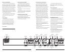
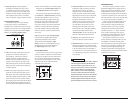
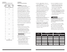
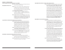
SPEAKER OUTPUTS
The 450/4v2 employs JL Audio’s exclusive
Regulated, Intelligent Power Supply (R.I.P.S.)
design. The operation of the R.I.P.S. system is
independent for each pair of channels. This
sophisticated power supply allows the amplifier
to produce its optimum power (150 watts x 2 for
channels 1&2 and 75 watts x 2 for channels 3&4)
over a wide range of speaker impedances.
Unlike conventional amplifiers that require
a specific impedance to produce optimum
power, the R.I.P.S.-equipped 450/4v2 gives
you the freedom to use a variety of speaker
configurations that achieve final nominal
impedances between 1.5 – 4Ω per channel in
stereo (without sacrificing power output or
sound quality). When bridged, each channel
QBJSXJMMPQUJNJ[FPVUQVUCFUXFFOo͙
The operation of the R.I.P.S. circuitry is
entirely automatic and adjusts itself every time
the amplifier is turned on according to the
lowest impedance present at the speaker load.
There are no user controls to configure. The
system operates through multiple stages of
JNQFEBODFPQUJNJ[BUJPODIPPTJOHUIFTUBHF
most appropriate to the actual impedance of the
speakers you connect to it.
CH
u
tput
R
e
B
a
B
a
O
c
tion
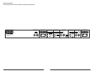
Bridged: 300W x 1 (3-8Ω)
Left Right
150W
(1.5-4)
150W
CH 1 & 2 Speaker Outputs
3)iFilter Freq. (Hz)w5IFGJMUFSGSFRVFODZ
markings surrounding this rotary control
are for reference purposes and are generally
accurate to within 1/3 octave or better. If you
would like to select the filter cutoff frequency
with a higher level of precision, consult the
charts in Appendix A (page 22) of this manual.
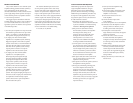
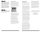
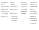
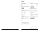
Preamp Output Section
The 450/4v2 incorporates a pass-through
preamp output section, so that additional
amplifiers can be added to the system. This pass-
through pre-amp output can be configured three
EJGGFSFOUXBZTVTJOHUIFTXJUDIMBCFMFEiSignal
FromwJOUIFiPreamp Output Sectionw
Left Output Right Output
Signal From
1 & 2
|
3 & 4
|
All
Preamp Output Section
B
1
CH
1
1) i1&2w5IFQSFBNQPVUQVUEFMJWFSTUIFTBNF
signal that is connected to the 450/4v2’s
CH 1&2 Inputs. This mode is useful for
feeding a subwoofer amplifier when the
450/4v2 is being used to drive front and rear
speaker systems. This preamp output mode
will track the signal level of CH 1&2, allowing
fading of the rear channels without affecting
the subwoofer level.
2) i 3&4w5IFQSFBNQPVUQVUEFMJWFSTUIFTBNF
signal that is connected to the 450/4v2’s CH
3&4 Inputs. This mode is useful for feeding a
subwoofer amplifier when the 450/4v2 is being
used to drive front and rear speaker systems.
This preamp output mode will track the signal
level of CH 3&4, allowing fading of the front
channels without affecting the subwoofer level.
3) iALLw5IJTNPEFEFMJWFSTBTVNPGUIFTJHOBMT
CFJOHGFEUPUIFiCH 1&2 Input SectionwBOE
iCH 3&4 Input SectionwPGUIFBNQMJGJFS
The Preamp Output signal is not affected by
UIFiLF BoostwPSiInfrasonic FilterwQSPDFTTJOH
selected for the amplifier or by any crossover
filter selected (if the input signal is full-range,
the preamp output will be full-range). When
the 450/4v2 is being used to drive front and
rear speaker systems, this preamp output mode
will deliver a summed front/rear signal to the
subwoofer amplifier, while permitting fading
of the front and rear speaker systems from the
source unit.
Note5IFTJHOBMMFWFMPGUIFiPreamp Outputw
is always low level regardless of the voltage
applied to this amplifier’s inputs and the
setting chosen on this amplifier’s “Input
Range” switch. A JL Audio amplifier receiving
signal from this preamp output should have
its “Input Range” switch set to “Low”.
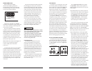
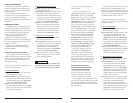
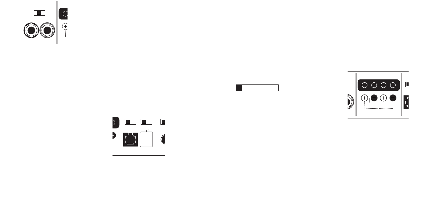
CH 1 & 2 Bass Control
This section provides two basic bass processing
tools for CH 1&2: a 24 dB/octave infrasonic filter
BU)[BOEBE#CPPTUDJSDVJUDFOUFSFEBU
)["DUJWBUJPOPGFJUIFSGFBUVSFBVUPNBUJDBMMZ
sums the CH 1&2 input signals to mono. (These
features should only be used when driving
subwoofer(s) from CH 1&2).
CH 1CH 1 & 2 Bass Control
Remote
Bass Port
Freq
.
x1
Infrasonic Filter
Off
|
30Hz
Bass EQ
Off
|
On
50
60
75
Filter
F
Either
feature
sums the
CH 1&2 input
signals to
mono when
activated.
u
ts