


12 | JL Audio - 450/4v2 Owner’s Manual
13
STATUS INDICATOR LIGHTS /
PROTECTION CIRCUITRY
There are three status indicator lights on the
top of the amplifier. These are as follows:
1)iPowerwGreen): lights to indicate that the
amplifier is turned on and operating normally.
2)iThermalwRed): lights to indicate that the
amplifier has exceeded its safe operating
temperature, putting the amplifier into a self-
protection mode, which reduces the power
output of the amplifier. The red light will shut
off and the amplifier will return to normal,
full-power operating mode if the heat sink
temperature drops back to a safe level.
3)iLow wAmber): lights to indicate that the
impedance of the speaker load connected to
the amplifier is lower than the optimum load
impedance range for the amplifier. When
this light is on, a protection circuit engages
and reduces the power output of CH 1&2
or CH 3&4, depending on which channel is
experiencing the problem. The amber indicator
will also light when a short-circuit is detected
in the speaker wiring (this can be a short
between the positive and negative speaker
wires or between either speaker wire and the
vehicle chassis). This can be used to diagnose
a short-circuit by only connecting one of the
amplifier sections at a time (CH 1&2 and CH
5IFBNCFS-&%XJMMMJHIUXIFOZPV
connect the section that is experiencing the
problem and turn the volume up.
There is only one condition that will shut
down an undamaged 450/4v2 completely…
If battery voltage drops below 10 volts, the
entire amplifier will shut itself off. The green
i1PXFSwJOEJDBUPSPOUIFUPQPGUIFBNQMJGJFSXJMM
turn off when this occurs. The amplifier will turn
back on when voltage climbs back above 10 volts.
This may happen in a rapid cycle when bass-
heavy program material causes a weak charging
system to dip below 10 volts momentarily. If this
is happening in your system, have your charging
system inspected to make sure it is working
properly. For information on troubleshooting this
amplifier, refer to Appendix C (page 24).
SERVICING YOUR JL AUDIO AMPLIFIER
If your amplifier fails or malfunctions, please
SFUVSOJUUPZPVSBVUIPSJ[FE+-"VEJPEFBMFSTP
that it may be sent in to JL Audio for service.
There are no user serviceable parts or fuses inside
the amplifier. The unique nature of the circuitry
in the JL Audio amplifiers requires specifically
USBJOFETFSWJDFQFSTPOOFM%POPUBUUFNQU
to service the amplifier yourself or through
VOBVUIPSJ[FESFQBJSGBDJMJUJFT5IJTXJMMOPUPOMZ
void the warranty, but may result in the creation
of more problems within the amplifier.
If you have any questions about the installation or
setup of the amplifier not covered in this manual,
please contact your dealer or technical support.
JL Audio Technical Support:
(954) 443-1100
9:00 AM – 5:30 PM (Eastern Time Zone)
Monday - Friday
IMPORTANT
!
If you connect a load higher than 4 nominal
per channel in stereo mode (or 8 in bridged
mode), power will drop by half with every
doubling of impedance above 4 stereo / 8
mono. If you connect a load lower than 1.5
nominal per channel in stereo mode (or 3 in
bridged mode, the amplifier protection
circuitry activates a “safe” mode which reduces
amplifier power to protect the circuitry from
failure (the yellow “Low ” LED lights to
indicate that this has happened). See page 13
for details.
IMPORTANT
!
Speaker loads below 1.5 nominal per channel
in stereo or 3 nominal in bridged mode are
not recommended and may cause the amplifier
output to distort excessively.
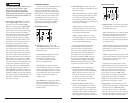
BRIDGING CONSIDERATIONS
Bridging is the practice of combining the
output of two amplifier channels to drive a single
load. When bridged, each channel produces
signals of equal magnitude, but opposite polarity.
The combined output of the two channels
provides twice the output voltage available from a
single channel. The 450/4v2 has been designed for
bridging of its channel pairs without the need for
input inversion adaptors.
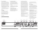
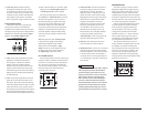
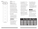
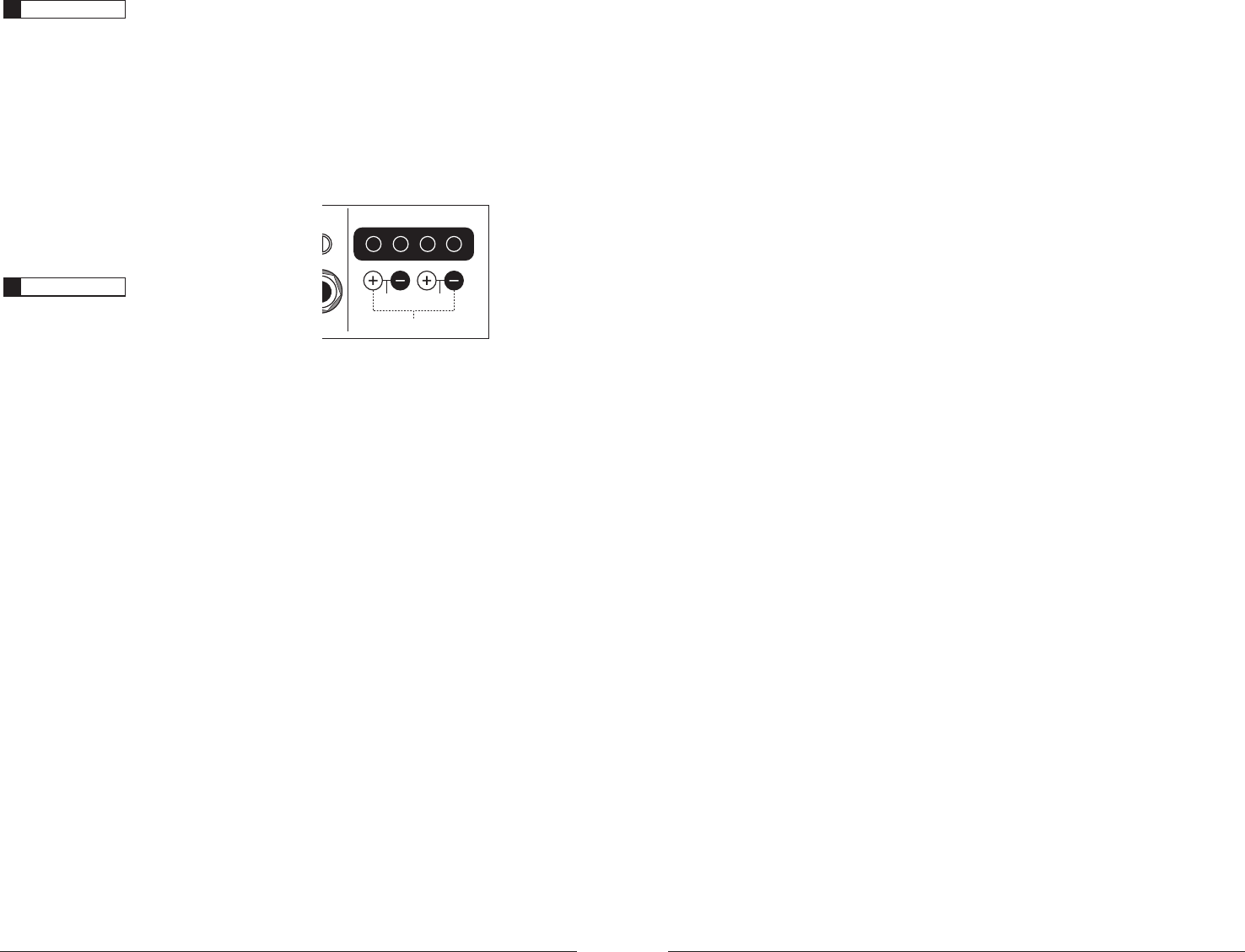
ction CH 3 & 4 Speaker Outputs
H
4
g
ht)
Sens.
Bridged: 150W x 1 (3-8Ω)
Left Right
75W
(1.5-4)
75W
5PCSJEHFBQBJSPGDIBOOFMTVTFUIFiLeft +w
BOEiRight –wTQFBLFSDPOOFDUPSTPOMZUIFiLeft
–wBOEiRight +wSFNBJOVOVTFE5IFODPOOFDU
a mono signal to both left and right RCA inputs
for that channel pair. This requires an RCA
i:"EBQUPSwMJLFUIF+-"VEJP&$4NPEFM
XB-CLRAICY-1F2M (sold separately).
When bridged, each channel pair will
deliver optimum power into a 3-8Ω load.
Operating bridged channel pairs into a load
lower than 3Ω is not recommended.
Because a bridged pair of channels requires
that both channels receive input, you need to
connect both left and right RCA inputs to the
bridged channel pair’s inputs. Connection of
only one RCA input will result in reduced power
output, increased distortion and can cause the
BNQMJGJFSUPPWFSIFBU%POPUEPUIJT*OTUFBEVTF
Bi:BEBQUPSwUPTQMJUUIFNPOPTJHOBMJOUPCPUI
left and right RCA inputs.