


14 | JL Audio - 450/4v2 Owner’s Manual
15
Crossover Setup for Bi-Amplified System
with one 450/4v2:
Once the input sections have been
DPOGJHVSFEBQQSPQSJBUFMZHPUPUIFiCH 1&2
Filter Sectionw4FMFDUix1wPOUIFiFreq.
RangewTXJUDIiLPwMPXQBTTPOUIFiFilter
TypewTXJUDIBOEi12dBwPSi24dBwPOUIF
iFilter Mode/SlopewTXJUDIBOEBOBQQSPQSJBUF
iFilter Freqw)[JTBHPPETUBSUJOH
point). You may also choose to activate the
iInfrasonic FilterwBOEPSiBass EQwGFBUVSFT
JOUIFiCH 1&2 Bass ControlwTFDUJPO1MFBTF
LFFQJONJOEUIBUBDUJWBUJPOPGUIFiBass EQw
NBZSFRVJSFMPXFSJOHUIF$)iInput
SenswUPNBJOUBJODMFBONBYJNVNPVUQVU
/FYUUVSOZPVSBUUFOUJPOUPUIFiCH
3&4 Input SectionwBOETFMFDUix1wPOUIF
iFreq. RangewTXJUDIiHPwIJHIQBTT
POUIFiFilter TypewTXJUDIBOEi12dBwPS
i24dBwPOUIFiFilter Mode/SlopewTXJUDI
BOEBOBQQSPQSJBUFiFilter Freq.wBHBJO
)[JTBHPPETUBSUJOHQPJOU
After proper adjustment of the CH
BOE$)iInput RangewBOE
iInput Sens.wDPOUSPMTVTJOHUIFNFUIPE
shown in Appendix B (page 22), you can
fine tune filter frequencies and slopes and
attenuate either pair of channels to achieve
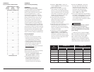
proper balance. For precise filter frequency
information refer to Appendix A (page 22).
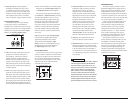
Bi-Amplified System with one
450/4v2 in four-channel mode and
a separate subwoofer amplifier
This configuration requires that
the separate subwoofer amplifier has
a built-in low-pass filter. All JL Audio
subwoofer amplifiers have this feature.
In this configuration, CH 1&2 of the 450/4v2
will drive front component speakers (stereo 150W
x 2) with high-pass filtering. CH 3&4 will drive
rear component speakers in stereo (75W x 2) with
high-pass filtering.
The separate amplifier will drive the subwoofer
system with low-pass filtering (select a filter
GSFRVFODZPG)[UPTUBSU5IFJOQVUTPGUIF
subwoofer amplifier may or may not be connected
to the preamp outputs of the 450/4v2, depending
on which connection option you choose.
Input connection options for a bi-amplifier
system with one 450/4v2 and a separate subwoofer
amplifier are as follows:
A) No User Adjustability
Req uired: a basic source unit or processor with
left and right stereo outputs.
Inp ut Connection s: a single pair of stereo source
unit outputs is connected to the CH 1&2
JOQVUTPGUIFWTFMFDUi2chwPOUIF
iInput ModewTXJUDIJOUIFiCH 1&2 Input
Sectionw$POOFDUUIFTVCXPPGFSBNQMJGJFS
inputs to the preamp outputs of the 450/4v2
4FMFDUi1&2wPOUIFi4JHOBM'SPNwTXJUDIJO
UIFiPreamp Output Sectionw
Res ult: the relative level of the LF and front and
rear HF channels will be fixed by the 450/4v2’s
iInput Sens.wTFUUJOHTBOEXJMMOPUCFVTFS
adjustable from the front of the vehicle.
B) Fade Subwoofer Level vs. HF Level
Req uired: a source unit or processor with front
and rear pairs of stereo outputs.
Inp ut Connection s: one stereo pair of source
unit outputs is connected to the CH 1&2
JOQVUTPGUIFWTFMFDUi2chwPOUIF
iInput ModewTXJUDIJOUIFiCH 1&2 Input
Sectionw5IFTFDPOETUFSFPQBJSPGTPVSDF
unit outputs is connected to the subwoofer
amplifier inputs. In this mode, the 450/4v2’s
preamp output is not used.
Res ult: with this option, the user has the ability
to fade the level of the subwoofer amplifier’s
input relative to the HF channels, but
cannot control front-to-rear fading of the
HF channels. The relative level of the front and
rear HF channels will be fixed by the 450/4v2’s
iInput Sens.wTFUUJOHTBOEXJMMOPUCFVTFS
adjustable from the front of the vehicle.
SYSTEM CONFIGURATIONS
The 450/4v2 is a very flexible amplifier, well-
suited for a multitude of system configurations.
In this section, the most likely configurations are
explained in detail.
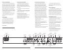
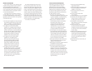
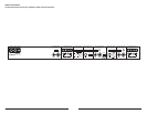
Once you have selected your desired
configuration, you can use the amplifier panel
drawings on the bottom of the following
pages to mark the required switch positions for
easy reference.
BIAMPLIFIED SYSTEMS
Bi-amplified systems are defined as systems
in which separate amplifier channels drive low-
frequency (LF) and high-frequency (HF) speakers
and are separately filtered to send appropriate
frequency ranges to each speaker system.
The most common application of bi-
amplification in mobile audio is to drive a
subwoofer system from one or more amplifiers or
channels and component speakers from separate
amplifiers or channels.
The 450/4v2 can be configured to drive a
bi-amplified system by itself or with a separate
subwoofer amplifier.
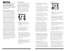
Bi-Amplified System with one 450/4v2
In this configuration, CH 1&2 of the 450/4v2
will drive subwoofers (stereo 150W x 2 or bridged
300W x 1) with low-pass filtering. CH 3&4 will
drive component speakers in stereo (75W x 2)
with high-pass filtering.
Input connection options for a bi-amplified system
with one 450/4v2 are as follows:
A) No User Adjustability
Req uired: a basic source unit or processor with
left and right stereo outputs.
Inp ut Connections: a single pair of stereo source
unit outputs connected to the CH 1&2 inputs of
UIFWTFMFDUi2chwPOUIFiInput Modew
TXJUDIJOUIFiCH 1&2 Input Sectionw
Res ult: the relative level of the LF and HF
DIBOOFMTXJMMCFGJYFECZUIFWTiInput
Sens.wTFUUJOHTBOEXJMMOPUCFVTFSBEKVTUBCMF
from the front of the vehicle.
B) Fade Subwoofer Level vs. HF Level
Req uired: a source unit or processor with front
and rear pairs of outputs.
Inp ut Connection s: the first stereo pair of source
unit outputs is connected to the CH 1&2
inputs of the 450/4v2. The second stereo pair
of source unit outputs is connected to the CH
JOQVUTTFMFDUi4chwPOUIFiInput Modew
TXJUDIJOUIFiCH 1&2 Input Sectionw
Res ult: in this mode, the user has the ability to
fade or control the level of the LF channels
relative to the HF channels via the source
unit’s fader control without exceeding the
maximum clean output level set by each
BNQMJGJFSTFDUJPOTiInput Sens.wDPOUSPMT
C) Subwoofer Level Control Only
Req uired: a source unit or processor with left,
right and subwoofer outputs.
Inp ut Connections: the main stereo pair of source
unit outputs is connected to the CH 3&4 inputs
of the 450/4v2. The source unit’s dedicated
subwoofer output is connected to the CH
JOQVUTTFMFDUi4chwPOUIFiInput Modew
TXJUDIJOUIFiCH 1&2 Input Sectionw
Res ult: in this mode, the user has the ability to
control the absolute level of the LF channels
relative to the HF channels.
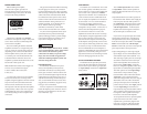
IMPORTANT
!
Set the CH 1&2 “Input Sens.” with the source
unit’s subwoofer level control set at 3/4 of full
output. See Appendix B (page 22) for details.