


18 | JL Audio - 450/4v2 Owner’s Manual
19
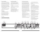
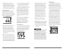
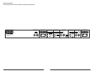
Crossover setup for bi-amplified 3.1 system with
one 450/4v2 and a separate subwoofer amplifier:
Once the input and preamp output sections have
CFFODPOGJHVSFEBQQSPQSJBUFMZHPUPUIFiCH
1&2 Filter Sectionw4FMFDUix1wPOUIFiFreq.
RangewTXJUDIiHPwIJHIQBTTPOUIFiFilter
TypewTXJUDIBOEi12dBwPSi24dBwPOUIF
iFilter Mode/SlopewTXJUDIBOEBOBQQSPQSJBUF
iFilter Freq.w)[JTBHPPETUBSUJOHQPJOU
5IFiInfrasonic FilterwBOEiBass EQwGFBUVSFT
cannot be used in this mode.
/FYUUVSOZPVSBUUFOUJPOUPUIFiCH 3&4
Input SectionwBOETFMFDUix1wPOUIFiFreq.
RangewTXJUDIiHPwIJHIQBTTPOUIFiFilter
TypewTXJUDIBOEi12dBwPSi24dBwPOUIFiFilter
Mode/SlopewTXJUDIBOEBOBQQSPQSJBUFiFilter
Freq.wBHBJO)[JTBHPPETUBSUJOHQPJOU
After proper adjustment of the 450/4v2’s
CH 1&2 and CH 3&4, and the subwoofer
BNQMJGJFSTiInput RangewBOEiInput Sens.w
you can fine tune filter frequencies and slopes
and attenuate the center channel or the left
BOESJHIUDIBOOFMQBJSXJUIUIFiInput Sens.w
controls to achieve proper balance. For proper
BEKVTUNFOUPGUIFiInput Sens.wDPOUSPMTPGUIF
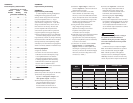
450/4v2 use the method shown in Appendix
B (page 22). For precise filter frequency
information for the 450/4v2 refer to Appendix
A (page 22). Refer to the subwoofer amplifier
owner’s manual for proper adjustments.
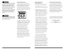
Bi-Amplified 5.1 System with
Multi-Channel Source, one 450/4v2 in
three-channel mode, a JL Audio 300/2
amplifier driving rear surround speakers
and a separate subwoofer amplifier
(JL Audio 500/1v2 or 1000/1v2 recommended)
This configuration is identical to the 3.1 system
configuration with Input Option A, except for
the addition of a JL Audio 300/2v2 two-channel
amplifier to drive rear surround speakers,
effectively creating a true 5.1 multi-channel
system with left-front, center-front, right-front,
left-rear and left-right channels.
The 300/2v2 in two-channel stereo mode is
perfectly matched to the 450/4v2 in three channel
Left, Center, Right mode. The system will deliver
150 W x 5 to power the component speaker
systems plus the output of an additional amplifier
to the subwoofer system.
To add this capability, connect the 300/2v2’s
inputs to the rear (surround) outputs of a multi-
channel processor or source unit and set the
WTiAmp FilterwJOiHPwNPEFXJUIB
i12dBwPSi24dBwGJMUFSTMPQF
IMPORTANT
!
The “Summed Center Channel” methods
outlined below do not create a true center
channel, they simply sum left and right signals
to the center speaker system. This is not as
desirable as a true center channel from a multi-
channel source, but it can be used to create a
convincing sound stage in some applications.
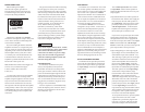
B) “Summed Center Channel”,
No User Adjustability
Req uired: a basic source unit or processor with
left and right stereo outputs.
Inp ut Connec tions: a single pair of stereo source
unit outputs, connected to the CH 1&2
JOQVUTPGUIFWTFMFDUi2chwPOUIF
iInput ModewTXJUDIJOUIFiCH 1&2 Input
Sectionw$POOFDUUIFTVCXPPGFSBNQMJGJFS
inputs to the preamp outputs of the 450/4v2
4FMFDUi1&2wPOUIFiSignal FromwTXJUDIJO
UIFiPreamp Output Sectionw
Res ult: the relative level of all channels will be
GJYFECZUIFWTiInput Sens.wTFUUJOHT
and will not be user adjustable from the front
of the vehicle.
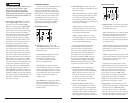
C) Fade Between “Summed Center Channel”
Level and Left/Right Level with Non-Fading
Subwoofer Level
Req uired: a source unit or processor with front
and rear pairs of stereo outputs.
Inp ut Connec tions: one pair of stereo source
unit outputs is connected to the CH 1&2
JOQVUTPGUIFWTFMFDUi4chwPOUIF
iInput ModewTXJUDIJOUIFiCH 1&2 Input
Sectionw"TFDPOEQBJSPGTPVSDFVOJU
outputs is connected to the CH 3&4 inputs.
Connect the subwoofer amplifier inputs to the
QSFBNQPVUQVUTPGUIFW4FMFDUiALLw
POUIFiSignal FromwTXJUDIJOUIFiPreamp
Output Sectionw
Res ult: with this option, the user has the ability
UPBEKVTUUIFSFMBUJWFMFWFMPGUIFi4VNNFE
$FOUFS$IBOOFMwJOQVUSFMBUJWFUPUIF-FGUBOE
Right channel pair via the source unit’s fader
control. Subwoofer is non-fading.
D) Fade Between “Summed Center Channel”
Level and Left/Right Level with Separate
Subwoofer Level Control
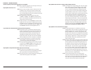
Req uired: a source unit or processor with
front and rear pairs of stereo outputs plus a
dedicated subwoofer output.
Inp ut Connec tions: one pair of stereo source
unit outputs is connected to the CH 1&2
JOQVUTPGUIFWTFMFDUi4chwPOUIF
iInput ModewTXJUDIJOUIFiCH 1&2 Input
Sectionw"TFDPOEQBJSPGTPVSDFVOJU
outputs is connected to the CH 3&4 inputs.
The source unit’s dedicated subwoofer output
is connected to the subwoofer amplifier’s
inputs. In this mode, the 450/4v2’s preamp
output is not used.
Res ult: with this option, the user has the ability to
GBEFCFUXFFOUIFi4VNNFE$FOUFS$IBOOFMw
level and the Left and Right channel levels via
the source unit’s fader control and also has
the ability to control the absolute level of the
subwoofer channel relative to the three HF
channels with the source unit’s subwoofer
level control.
IMPORTANT
!
Set the subwoofer amplifier’s “Input Sens.”
with the source unit’s subwoofer level
control set at 3/4 of full output. Refer to the
subwoofer amplifier owner’s manual for
proper adjustment.