


28 | JL Audio - 450/4v2 Owner’s Manual
29
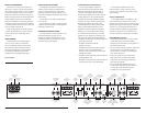
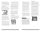
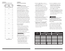
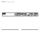
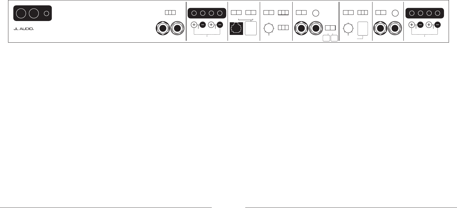
INSTALLATION NOTES:
Use this diagram to document your amplifier’s switch and control positions.
+12VDC Ground Remote CH 1 & 2 Filter SectionCH 1 & 2 Bass Control CH 3 & 4 Filter SectionCH 1 & 2 Input Section CH 3 & 4 Input Section CH 3 & 4 Speaker Outputs
Left Output Right Output HP Filter Freq. (Hz)
Remote
Bass Port
CH 3
(Left)
CH 4
(Right)
CH 1
(Left)
CH 2
(Right)
Freq. Range
Input Voltage Input Sens.Input Sens.
Input Mode
2ch
|
4ch
Filter Type
LP
|
BP
|
HP
x1
|
x10 Low
|
High
Input Voltage
Low
|
High
High-Pass Filter
Off
|
12dB
|
24dB
Freq. Range
Filter Mode
|
Slope
x1
|
x10 Off
|
12dB
|
24dB
Infrasonic Filter
Off
|
30Hz
Bass EQ
Off
|
On
Signal From
1 & 2
|
3 & 4
|
All
50
60
75
95
130
200
50050
60
75
95
130
200
500
Filter Freq. (Hz)
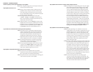
450/4v2
Four-Channel System Amplifier
Preamp Output Section
1 & 2
Inputs
Only
Either
feature
sums the
CH 1&2 input
signals to
mono when
activated.
1 & 2
and
3 & 4
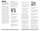
Bridged: 150W x 1 (3-8Ω)
Left Right
75W
(1.5-4)
75W
Bridged: 300W x 1 (3-8Ω)
Left Right
150W
(1.5-4)
150W
CH 1 & 2 Speaker Outputs
Also sets
low-pass
cutoff for
CH 1 & 2
Bandpass
Filter
(if selected)