


6 | JL Audio - 450/4v2 Owner’s Manual
7
TURNON LEAD
The 450/4v2 uses a conventional +12V remote
turn-on lead, typically controlled by the source
unit’s remote turn-on output. The amplifier will
UVSOPOXIFO7JTQSFTFOUBUJUTiRemotew
input and turn off when +12V is switched off. If
a source unit does not have a dedicated remote
turn-on output, the amplifier’s turn-on lead can
be connected to +12V via a switch that derives
power from an ignition-switched circuit.
5IFWTiRemotewUVSOPODPOOFDUPS
is designed to accept 18 AWG – 8 AWG wire. 12
AWG is more than adequate for this purpose.
To connect the remote turn-on wire to the
amplifier, first back out the set screw on the top
of the amplifier, using the supplied hex wrench.
Strip 1/2 inch (12mm) of wire and insert the
bare wire into the receptacle on the front panel
of the amplifier, seating it firmly so that no bare
wire is exposed. When using smaller wire, it may
be necessary to strip 1 inch of insulation from
the wire and fold the bare wire in half prior to
insertion. While holding the wire in the terminal,
tighten the set screw firmly, taking care not to
strip the head of the screw and making sure that
the wire is firmly gripped by the set screw.
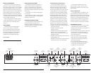
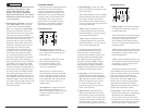
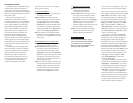
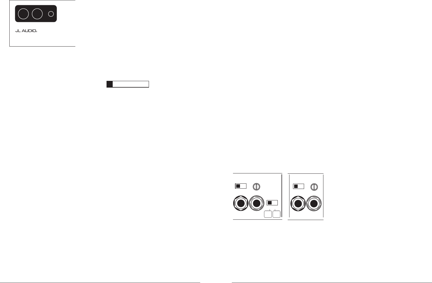
CH 1&2 / CH 3&4 INPUT SECTIONS
The 450/4v2 has two separate input sections,
one for CH 1&2 and another for CH 3&4. Each
section contains a pair of RCA-type input jacks,
BOiInput VoltagewTXJUDIBOEBOiInput Sens.w
rotary control.
CH 1 & 2 Input Section
CH 1
(Left)
CH 2
(Right)
Input Sens.
Input Mode
2ch
|
4ch
Input Voltage
Low
|
High
1 & 2
Inputs
Only
1 & 2
and
3 & 4
CH 3 & 4 Input Section
CH 3
(Left)
CH 4
(Right)
Input Voltage Input Sens.
Low
|
High
5IFiCH 1&2 Input SectionwBMTPDPOUBJOT
BOiInput ModewTXJUDIUPBMMPXPQFSBUJPOPG
all four amplifier channels with one or two pairs
of input signals.
1) Input Mode Switch: If you wish to operate all
four channels of the 450/4v2 with a single pair
PGTUFSFPJOQVUTTFMFDUUIFi2chwQPTJUJPOPO
UIFiInput ModewTXJUDIBOEDPOOFDUBTJOHMF
pair of input cables to the input jacks in the
iCH 1&2 Input Sectionw*OUIJTNPEFUIF
amplifier will route the signals connected to
the CH 1&2 inputs to CH 3&4 as well.
If you wish to use separate inputs for CH 1&2
and CH 3&4 (to allow front-to-rear fading, for
example) and the source unit is equipped with
GSPOUBOESFBSPVUQVUTTFMFDUi4chwPOUIFiInput
ModewTXJUDIMPDBUFEJOUIFiCH 1&2 Input
Sectionw*OUIJTNPEFZPVNVTUDPOOFDUTFQBSBUF
pairs of input cables to each input section.
2) Input Voltage Range: A wide range of signal
input voltages can be accommodated by each
of the 450/4v2’s input sections (200mV – 8V).
This wide range is split up into two sub-ranges,
accessible via switches located in each input
section of the amplifier. Be aware that each
JOQVUTFDUJPOTiInput VoltagewTXJUDIXJMM
have to be configured, regardless of how many
input cables are actually feeding the amplifier.
5 IF iLowwQPTJUJPOPOFBDIiInput Voltagew
switch selects an input sensitivity range
between 200mV and 2V. This means that the
iInput Sens.wSPUBSZDPOUSPMXJMMPQFSBUF
within that voltage window. If you are using an
aftermarket source unit, with conventional
preamp-level outputs, this is most likely the
QPTJUJPOUIBUZPVXJMMVTF5IFiHighwQPTJUJPO
POFBDIiInput VoltagewTXJUDITFMFDUTBO
input sensitivity range between 800mV and 8V.
This is useful for certain high-output preamp
level signals as well as speaker-level output
from source units and small amplifiers.
To use speaker-level sources, splice the speaker
output wires of the source unit or small
amplifier onto a pair of RCA plugs for each
input pair or use the JL Audio ECS Speaker
Wire to RCA adaptor (XB-CLRAIC2-SW).
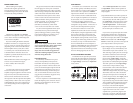
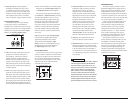
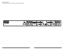
POWER CONNECTIONS
Before installing the amplifier,
disconnect the negative (ground) wire
from the vehicle’s battery. This will prevent
accidental damage to the system, the vehicle
and your body during installation.
+12VDC Ground Remote
450/ 4v2
Four-Channel System Amplifier
5IFWTi+12 VDCwBOEiGroundw
connections are designed to accept 4 AWG power
wire. 4 AWG is the only recommended power
XJSFTJ[FGPSUIJTBNQMJGJFS
If you are installing the 450/4v2 with other
amplifiers and wish to use a single main power
wire, use 2 AWG or 1/0 AWG main power wire
(depending on the overall current demands of
all the amplifiers in the system). This 2 AWG
or 1/0 AWG power wire should terminate into
a distribution block mounted as close to the
amplifiers as possible and should connect to the
450/4v2 with 4 AWG power wire.
Note: Smaller AWG numbers mean bigger wire
and vice-versa (1/0 AWG is the largest,
2 AWG is smaller, then 4 AWG, then
8 AWG, etc.).
To connect the power wires to the amplifier,
first back out the set screw on the top of the
amplifier, using the supplied 2.5 mm hex wrench.
Strip 1/2 inch (12 mm) of insulation from the
end of each wire and insert the bare wire into
the receptacle on the front panel of the amplifier,
seating it firmly so that no bare wire is exposed.
While holding the wire in place, tighten the set
screw firmly, taking care not to strip the head
of the screw.
The ground connection should be made using
the same gauge wire as the power connection
(4 AWG) and should be kept as short as possible,
while accessing a solid piece of sheet metal in the
vehicle. The surface of the sheet metal should
be sanded at the contact point to create a clean,
metal-to-metal connection between the chassis
and the termination of the ground wire. For
optimal grounding, we recommend the use
of a JL Audio ECS master ground lug
(XB-MGLU). Alternatively, a sheet metal
screw or bolt can be used with a star washer.
Any wires run through metal barriers (such
as firewalls), must be protected with a high
quality insulating grommet to prevent damage
to the insulation of the wire. Failure to do so
may result in a dangerous short circuit.
IMPORTANT
!
Many vehicles employ small (10 AWG - 6 AWG)
wire to ground the battery to the vehicle chassis
and to connect the alternator’s positive
connection to the battery. To prevent voltage
drops, these wires should be upgraded to 4
AWG when installing amplifier systems with
main fuse ratings above 60A.
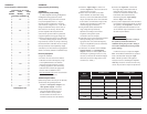
Fuse Requirements
It is absolutely vital that the main power
wire(s) to the amplifier(s) in the system be
fused within 18 inches (45 cm) of the positive
battery post connection. The fuse value at each
power wire should be high enough for all of the
equipment being run from that power wire. If
only the 450/4v2 is being run from that power
wire, we recommend a 60A fuse be used. AGU
(big glass fuse) or MaxiFuse™ (big plastic-body
fuse) types are recommended.
No fuse is required or recommended directly
before the amplifier power connection. If one is
desired, we recommend the use of a 60A AGU
fuse or MaxiFuse™ type.