


2 | JL Audio - 450/4v2 Owner’s Manual
3
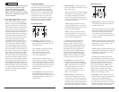
Cooling Efficiency Considerations:
Your JL Audio amplifier employs an
advanced type of heat management, called
RealSink™. This feature takes advantage of
convection and radiation effects to remove
heat from the amplifier circuitry. For optimum
cooling performance, the vertical heat sinks
located at the back of the amplifier should be
exposed to as large a volume of air as possible.
Enclosing the amplifier in a small, poorly
ventilated chamber can lead to excessive heat
build-up and degraded performance. If an
installation calls for an enclosure around the
amplifier, we recommend that this enclosure
be ventilated with the aid of a fan. In normal
applications, fan-cooling is not necessary, but
you still need to follow some basic guidelines:
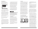
t"NQMJGJFSNPVOUFEWFSUJDBMMZXJUIIFBUTJOLGJOT
pointing up: Optimum
t"NQMJGJFSNPVOUFEIPSJ[POUBMMZ
right side up: Good
t"NQMJGJFSNPVOUFEIPSJ[POUBMMZCVUVQTJEF
down: Fair (not recommended if there is
less than 1 inch (2.5 cm) clearance above the
amplifier heat sinks)
t"NQMJGJFSNPVOUFEWFSUJDBMMZXJUIIFBUTJOLGJOT
pointing laterally: Fair
t"NQMJGJFSNPVOUFEWFSUJDBMMZXJUIIFBUTJOLGJOT
pointing down: Poor (not recommended)
If mounting the amplifier under a seat,
make sure there is at least 1 inch (2.5 cm) of
space above the amplifier’s outer shell to permit
proper cooling.
Safety Considerations:
Your amplifier needs to be installed in a dry,
well-ventilated environment and in a manner
which does not interfere with your vehicle’s safety
equipment (air bags, seat belt systems, ABS brake
systems, etc.). You should also take the time to
securely mount the amplifier using appropriate
hardware so that it does not come loose in the
event of a collision or a sudden jolt to the vehicle.
Stupid Mistakes to Avoid:
tCheck before drilling any holes in your vehicle
to make sure that you will not be drilling
through a gas tank, brake line, wiring harness or
other vital vehicle system.
t%POPUSVOTZTUFNXJSJOHPVUTJEFPSVOEFSOFBUI
the vehicle. This is an extremely dangerous
practice which can result in severe damage to
your vehicle and person.
t1SPUFDUBMMTZTUFNXJSFTGSPNTIBSQNFUBM
edges and wear by carefully routing them,
tying them down and using grommets and
loom where appropriate.
t%POPUNPVOUUIFBNQMJGJFSJOUIFFOHJOF
compartment, under the vehicle, on the roof
or in any other area that will expose the
amplifier circuitry to the elements.
PROTECT YOUR HEARING!
We value you as a long-term customer. For
that reason, we urge you to practice restraint in
the operation of this product so as not to damage
your hearing and that of others in your vehicle.
Studies have shown that continuous exposure to
high sound pressure levels can lead to permanent
(irreparable) hearing loss. This and all other
high-power amplifiers are capable of producing
such high sound pressure levels when connected
to a speaker system. Please limit your continuous
exposure to high volume levels.
While driving, operate your audio system in
a manner that still allows you to hear necessary
noises to operate your vehicle safely (horns,
sirens, etc.).
SERIAL NUMBER
In the event that your amplifier requires
service or is ever stolen, you will need to
have a record of the product’s serial number.
Please take the time to enter that number in
the space provided below. The serial number
can be found on the bottom panel of the
amplifier and on the amplifier packaging.
Serial Number:
INSTALLATION APPLICATIONS
This amplifier is designed for operation in
vehicles with 12V, negative-ground electrical
systems. Use of this product in vehicles with
positive ground and/or voltages other than 12V
may result in damage to the product and will void
the warranty.
This product is not certified or approved for
use in aircraft.
%POPUBUUFNQUUPiCSJEHFwUIFPVUQVUTPGUIJT
amplifier with the outputs of a second amplifier,
including an identical one.
PLANNING YOUR INSTALLATION
It is important that you take the time to read
this manual and that you plan out your
installation carefully. The following are some
considerations that you must take into account
when planning your installation.
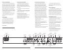
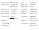
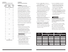
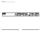
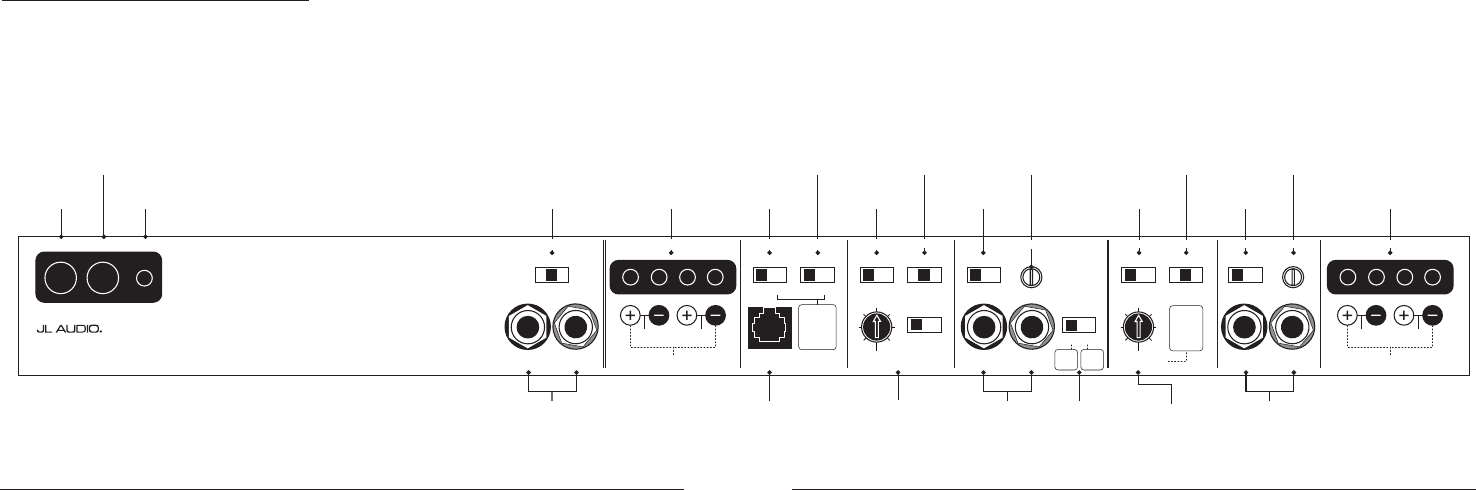
+12VDC Ground Remote CH 1 & 2 Filter SectionCH 1 & 2 Bass Control CH 3 & 4 Filter SectionCH 1 & 2 Input Section CH 3 & 4 Input Section CH 3 & 4 Speaker Outputs
Left Output Right Output HP Filter Freq. (Hz)
Remote
Bass Port
CH 3
(Left)
CH 4
(Right)
CH 1
(Left)
CH 2
(Right)
Freq. Range
Input Voltage Input Sens.Input Sens.
Input Mode
2ch
|
4ch
Filter Type
LP
|
BP
|
HP
x1
|
x10 Low
|
High
Input Voltage
Low
|
High
High-Pass Filter
Off
|
12dB
|
24dB
Freq. Range
Filter Mode
|
Slope
x1
|
x10 Off
|
12dB
|
24dB
Infrasonic Filter
Off
|
30Hz
Bass EQ
Off
|
On
Signal From
1 & 2
|
3 & 4
|
All
50
60
75
95
130
200
50050
60
75
95
130
200
500
Filter Freq. (Hz)
450/4v2
Four-Channel System Amplifier
Preamp Output Section
1 & 2
Inputs
Only
Either
feature
sums the
CH 1&2 input
signals to
mono when
activated.
1 & 2
and
3 & 4
Bridged: 150W x 1 (3-8Ω)
Left Right
Bridged: 300W x 1 (3-8Ω)
Left Right
CH 1 & 2 Speaker Outputs
Also sets
low-pass
cutoff for
CH 1 & 2
Bandpass
Filter
(if selected)
CH 1&2
Filter Slope
Selection / Defeat
(pg. 9)
Infrasonic Filter
On/O Switch
(pg. 11)
Preamp Output
Signal Selector
(pg. 10)
Left and Right
Preamp Output Jacks
(pg. 10)
Jack for
Remote Bass
Control Knob
(pg. 11)
CH 3&4
Input Voltage
Range Selector
(pg. 7)
Selects
2ch / 4ch
Input Mode
(pg. 7)
CH 3&4
HP Filter Slope
Selection / Defeat
(pg. 9)
CH 3&4
Filter Frequency
Range Selector
(pg. 9)
Selects CH 3&4
High-Pass Cuto
Frequency and Low-Pass
Cuto for CH 1&2 Bandpass
Filter
(pg. 10)
CH 3&4
Input Sensitivity
Control
(pg. 8)
CH 1&2
Left and Right
Input Jacks
(pg. 7)
CH 3&4
Left and Right
Input Jacks
(pg. 7)
Bass EQ
On/O Switch
(pg. 11)
CH 1&2
Filter Frequency
Range Selector
(pg. 9)
CH 1&2
Input Voltage
Range Selector
(pg. 7)
Remote Turn-On
Connector
(pg. 7)
Chassis Ground
Connector
(pg. 6)
+12 V Power
Connector
(pg. 6)
CH 1&2
Speaker Outputs
(pg. 11)
Selects CH 1&2
HP or LP Cuto
Frequency or HP Cuto
of Bandpass Filter
(pg. 8)
CH 3&4
Speaker Outputs
(pg. 11)
CH 1&2 Input
Sensitivity Control
(pg. 8)