


20 | JL Audio - 450/4v2 Owner’s Manual
21
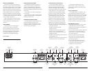
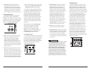
C) Subwoofer Level Control Only
Req uired: a source unit or processor
with left, right and dedicated
subwoofer outputs is required.
Inp ut Connec tions: one stereo pair of source
unit outputs is connected to the CH 1&2
JOQVUTPGUIFWTFMFDUi2chwPOUIF
iInput ModewTXJUDIJOUIFiCH 1&2 Input
SectionwBOEUIFTPVSDFVOJUTEFEJDBUFE
subwoofer output is connected to the
subwoofer amplifier inputs. In this mode, the
450/4v2’s preamp output is not used.
Res ult: the user has the ability to control the
absolute level of the subwoofer channel
relative to the MF and HF channels.
IMPORTANT
!
Set the subwoofer amplifier’s “Input
Sens.” with the source unit’s subwoofer
level control set at 3/4 of full output.
Refer to the subwoofer amplifier owner’s
manual for proper adjustment.
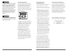
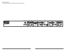
Crossover setup for tri-amplified 3.1 system with
one 450/4v2 and a separate subwoofer amplifier:
Once the input and preamp output sections have
CFFODPOGJHVSFEBQQSPQSJBUFMZHPUPUIFiCH 1&2
Filter SectionwPGUIFW5IFTFTFUUJOHT
will determine the high-pass cutoff and slope of
the bandpass filtering applied to the MF (mid-
GSFRVFODZDIBOOFMT4FMFDUix1wPOUIFiFreq.
RangewTXJUDIiBPwCBOEQBTTPOUIFiFilter
TypewTXJUDIBOEi12dBwPSi24dBwPOUIF
iFilter Mode/SlopewTXJUDIBOEBOBQQSPQSJBUF
iFilter Freq.w)[JTBHPPETUBSUJOHQPJOU
5IFiInfrasonic FilterwBOEiBass EQwGFBUVSFT
cannot be used in this mode.
/FYUUVSOZPVSBUUFOUJPOUPUIFiCH 3&4
Input Sectionw5IFTFTFUUJOHTXJMMEFUFSNJOF
the high-pass cutoff and slope of the high pass
filtering applied to the HF (high-frequency)
channels as well as the low-pass cutoff frequency
and slope for the MF channels’ bandpass filter.
4FMFDUix1wPOUIFiFreq. RangewTXJUDIJGZPVS
desired MF to HF crossover frequency is below
)[4FMFDUix10wPOUIFiFreq. RangewTXJUDI
if your desired MF to HF crossover frequency
JTBCPWF)[4FMFDUiHPwIJHIQBTTPOUIF
iFilter TypewTXJUDIBOEi12dBwPSi24dBw
POUIFiFilter Mode/SlopewTXJUDIBOEBO
BQQSPQSJBUFiFilter Freq.w
After proper adjustment of the 450/4v2’s CH
1&2 and CH 3&4, and the subwoofer amplifier’s
iInput RangewBOEiInput Sens.wZPVDBOGJOF
tune filter frequencies and slopes and attenuate
the LF, MF and HF channel pair or with the
iInput Sens.wDPOUSPMTUPBDIJFWFQSPQFSCBMBODF
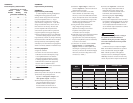
'PSQSPQFSBEKVTUNFOUPGUIFiInput Sens.w
controls of the 450/4v2 use the method shown in
Appendix B (page 22). For precise filter frequency
information for the 450/4v2 refer to Appendix
A (page 22). Refer to the subwoofer amplifier
owner’s manual for proper adjustments.
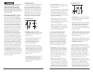
TRIAMPLIFIED SYSTEMS
Tri-amplified systems are defined as systems
in which separate amplifier channels drive
low-frequency (LF), mid-frequency (MF) and
high-frequency (HF) speakers and are separately
filtered to send appropriate frequency ranges to
each speaker system.
The most common application of tri-
amplification in mobile audio is to drive a
subwoofer system from one or more amplifiers
or channels (LF channels), mid-range speakers
from a separate amplifier or set of channels
(MF channels) and high-frequency speakers
from a separate amplifier or set of channels
(HF channels). One such configuration is to
run subwoofers off the LF channel(s), mid-
bass speakers off the MF channels, and a
passively crossed over mid/high frequency
component speaker systems on the HF channels.
Another approach is to run subwoofers off the
LF channel(s), mid-woofers off the MF channels
and tweeters off the HF channels (all actively
crossed over).
By activating the CH 1&2 bandpass filter
feature, the 450/4v2 can easily be configured
to drive a tri-amplified system in conjunction
with a separate subwoofer amplifier that
includes a low-pass filter. CH 3&4 of the
450/1 will drive the HF speakers (75W x 2),
CH 1&2 will drive the MF speakers (150W
x 2) and the separate subwoofer amp(s)
will drive the LF speakers (subwoofers).
Input connection options for the Tri-Amplified
Stereo mode are as follows:
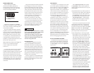
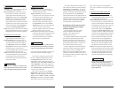
A) No User Adjustability
Req uired: a basic source unit or processor with
left and right stereo outputs.
Inp ut Connec tions: a single pair of stereo
source unit outputs is connected to the CH
JOQVUTPGUIFWTFMFDUi2chwPO
UIFiInput ModewTXJUDIJOUIFiCH 1&2
Input Sectionw4VCXPPGFSBNQMJGJFSJOQVUT
are connected to the preamp outputs of the
W4FMFDUi1&2wPOUIFiSignal Fromw
TXJUDIJOUIFiPreamp Output Sectionw
Res ult: the relative level of all channels will be
GJYFECZUIFWTiInput Sens.wTFUUJOHT
and will not be user adjustable from the front
of the vehicle.
B) Fade Subwoofer Level vs. MF/HF Level
Req uired: a source unit or processor with front
and rear pairs of outputs is required.
Inp ut Connec tions: one stereo pair of source
unit outputs is connected to the CH 1&2
JOQVUTPGUIFWTFMFDUi2chwPOUIF
iInput ModewTXJUDIJOUIFiCH 1&2 Input
SectionwBOEUIFTFDPOETUFSFPQBJSPGTPVSDF
unit outputs is connected to the subwoofer
amplifier inputs. In this mode, the 450/4v2’s
preamp output is not used.
Res ult: the user has the ability to adjust the level
of the subwoofer channel relative to the mid
and high-frequency channels via the source
unit’s fader control, without exceeding the
maximum clean output level set by each
BNQMJGJFSTFDUJPOTiInput Sens.wDPOUSPMT