


4 | JL Audio - 450/4v2 Owner’s Manual
5
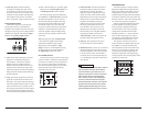
TYPICAL INSTALLATION SEQUENCE
The following represents the sequence for
a typical amplifier installation, using an
aftermarket source unit or OEM Interface
processor (like the CleanSweep® CL441dsp).
Additional steps and different procedures may
be required in some applications. If you have
BOZRVFTUJPOTQMFBTFDPOUBDUZPVSBVUIPSJ[FE
JL Audio dealer for assistance.
%JTDPOOFDUUIFOFHBUJWFCBUUFSZQPTU
connection and secure the disconnected cable
to prevent accidental re-connection during
installation. This step is not optional!
2) Run power wire (minimum 4 AWG)
from the battery location to the amplifier
mounting location, taking care to
route it in such a way that it will not be
damaged and will not interfere with
vehicle operation. Use 2 AWG or 1/0
AWG power wire if additional amplifiers
are being installed with the 450/4v2.
3) Connect power wire to the positive battery
post. Fuse the wire with an appropriate fuse
block (and connectors) within 18 inches (45
cm) wire length of the positive battery post.
This fuse is essential to protect the vehicle.
%POPUJOTUBMMUIFGVTFVOUJMUIFQPXFSXJSF
has been connected to the amplifier.
4) Run signal cables (RCA cables) and remote
turn-on wire from the source unit to the
amplifier mounting location.
5) Run speaker wire from the speaker systems to
the amplifier mounting location.
6) Find a good, solid metal grounding point
close to the amplifier and connect the
negative power wire to it using appropriate
hardware. Use minimum 4 AWG power wire,
no longer than 36 inches (90 cm) from the
amplifier to the ground connection point. In
some vehicles, it may be necessary to upgrade
the battery ground wire. (See page 6 for
important notice).
7) Securely mount the amplifier using
appropriate hardware.
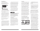
8) Connect the positive and negative power
wires to the amplifier. A fuse near the
amplifier is not necessary.
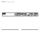
9) Connect the remote turn-on wire
to the amplifier.
10) Connect the RCA input cables
to the amplifier.
11) Connect the speaker wires to the amplifier.
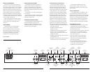
12) Carefully review the amplifier’s control
settings to make sure that they are set
according to the needs of the system.
13) Install power wire fuse (60A for a
single 450/4v2) and reconnect the negative
battery post terminal.
14) Turn on the source unit at a low level
to double-check that the amplifier is
configured correctly. Resist the temptation
to crank it up until you have verified the
control settings.
15) Make necessary adjustments to the input
sensitivity controls to obtain the right
overall output and the desired balance
in the system. See Appendix B (page 22)
for the recommended input sensitivity
setting method.
16) Enjoy the fruits of your labor with your
favorite music.
PRODUCT DESCRIPTION
The JL Audio 450/4v2 is a four-channel system
BNQMJGJFSVUJMJ[JOHQBUFOUFE"CTPMVUF4ZNNFUSZ
Class AB technology for all channels. All
channels benefit from JL Audio’s exclusive R.I.P.S.
QPXFSTVQQMZEFTJHOXIJDIPQUJNJ[FTUIFPVUQVU
of each channel pair for any impedance between
1.5 and 4 ohms per channel.
The staggered power distribution of the 1&2
and 3&4 channel pairs (150W x 2 for CH 1&2 and
75 x 2 for CH 3&4) allows for a wide variety of
application options. The 450/4v2 can be operated
in the following modes:
1) As a full-system amplifier in bi-amp mode with
CH 1&2 driving subwoofers in low-pass mode
(150W x 1 or 300W x 1) and CH 3&4 driving
main speakers in high-pass mode (75W x 2).
2) As a high power four-channel satellite
amplifier in a bi-amplified system, delivering
high-passed signals to front and rear speaker
systems. In this mode, we recommend that CH
1&2 drive the front speaker systems and CH
3&4 drive the rear speaker systems. Preamp
outputs permit connection of a separate
amplifier to drive the subwoofer system.
3) As a high power four-channel satellite
amplifier in a tri-amplified system,
delivering band-passed signals through
CH 1&2 to mid-bass speakers and high-
passed signals through CH 3&4 to mid-
range/ tweeter speaker systems. Preamp
outputs permit connection of a separate
amplifier to drive the subwoofer system.
4) As a high power three-channel satellite
amplifier, delivering 150W x 3 at 4Ω in high-
pass mode to left, center and right speaker
systems. This requires bridging the outputs of
CH 3&4 to create an equal power third channel
to complement CH 1&2. Preamp outputs
permit connection of a separate amplifier to
drive the subwoofer system.
The 450/4v2’s flexible input and crossover
sections permit operation with a wide variety
of source units and system configurations. The
450/4v2 can operate with a single pair of stereo
inputs or with separate inputs for CH 1&2 and
CH 3&4, if the source unit is equipped with front
and rear outputs. The 450/4v2’s preamp output
can send pass-through signals from the CH 1&2
inputs only or the CH 3&4 inputs only or it can
sum all four input channels to feed a subwoofer
amplifier. This latter mode allows for non-fading
sub-bass with front to rear satellite fading.
As we said, it’s very flexible.