


22 | JL Audio - 450/4v2 Owner’s Manual
23
3) 4XJUDIUIFiInput VoltagewUPiLowwBOE
UVSOUIFiInput Sens.wDPOUSPMPOCPUITFUTPG
channels all the way down.
4) Set the source unit volume to 3/4 of full
volume. If either set of channels is being
driven by a source unit’s dedicated subwoofer
output, also adjust the source unit’s subwoofer
level control to 3/4 of maximum output. This
will allow for reasonable gain overlap with
moderate clipping at full volume.
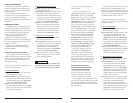
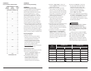
5) Using the chart below, determine the
target voltage for input sensitivity
adjustment according to the nominal
impedance of the speaker system
connected to each set of outputs.
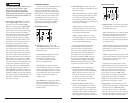
6) Verify that you have disconnected the speakers
before proceeding. Play a track with an
appropriate sine wave (within the frequency
range to be amplified by each set of channels)
at 3/4 source unit volume.
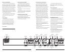
7)$POOFDUUIF"$WPMUNFUFSUPUIFiCH 1&2
Speaker OutputswPSiCH 3&4 Speaker
OutputswDPOOFDUPSTPGUIFBNQMJGJFS*GUIF
channel pair is operating in stereo, it is only
necessary to measure one channel. If bridged,
make sure you test the voltage at the correct
connectors (L+ and R–).
8)*ODSFBTFUIFiInput SenswDPOUSPMVOUJM
the target voltage is delivered for that set
of channels. If excessive voltage is read
on either set of channels with the control
at minimum (full counterclockwise),
TXJUDIUIFBQQSPQSJBUFiInput Voltagew
TXJUDIUPiHighwBOESFBEKVTU
9) Once you have adjusted each set of channels to
its maximum unclipped output level, reconnect
UIFTQFBLFST5IFiInput Sens.wDPOUSPMTDBO
now be adjusted downward if either or both
sets of channels requires attenuation to achieve
the desired system balance.
IMPORTANT
!
Do not increase any “Input Sens.” setting in
the system beyond the maximum level
established during this procedure. Doing so
will result in audible distortion and possible
speaker damage.
*UXJMMCFOFDFTTBSZUPSFBEKVTUUIFiInput
Sens.wGPSUIFBGGFDUFEDIBOOFMTJGBOZFRVBMJ[FS
CPPTUJTBDUJWBUFEBGUFSTFUUJOHUIFiInput
Sens.wXJUIUIJTQSPDFEVSF5IJTBQQMJFTUP
any EQ boost circuit, including the amplifier’s
iBass EQwBOETPVSDFVOJUUPOFDPOUSPMTPS&2
circuits. EQ cuts will not require re-adjustment.
Nom.
Impedance
CHANNELS 1&2 CHANNELS 3&4
Stereo Bridged Stereo Bridged
8 24.5 V 49.0 V 17.3 V 34.6 V
6 24.5 V 42.4 V 17.3 V 30.0 V
4 24.5 V 34.6 V 17.3 V 24.5 V
3 21.2 V 30.0 V 15.0 V 21.2 V
2 17.3 V
not recommended
12.2 V
not recommended
1.5 15.0 V
not recommended
10.6 V
not recommended
APPENDIX A:
Precise Frequency Selection Chart
“FILTER FREQ” CH 1&2 / CH 3&4
Detent Panel Actual
Number Marking Freq.
Full counter-clockwise: 58
01 ............................58
02 ...........“50”............58
03 ............................58
04 ............................58
05 ............................59
06 ............................60
07 ............................61
08 ...........“60”............63
09 ............................65
10 ............................67
11 ............................69
12 ............................71
13 ............................74
14 ...........“75”............77
15 ............................80
16 ............................82
17 ............................85
18 ............................90
19 ............................93
20 ...........“95”............97
21 ...........................102
22 ...........................107
23 ...........................113
24 ...........................120
25 ...........................127
26 ..........“130” ..........135
27 ...........................143
28 ...........................153
29 ...........................171
30 ...........................182
31 ...........................201
32 ..........“200” ..........223
33 ...........................253
34 ...........................289
35 ...........................337
36 ...........................404
37 ...........................474
38 ..........“500” ..........514
Full-clockwise: 542
APPENDIX B:
Input Sensitivity Level Setting
APPENDIX A:
Input Sensitivity Level Setting
+-"VEJPBNQMJGJFSTVUJMJ[JOHUIF3FHVMBUFE
Intelligent Power Supply (R.I.P.S.) allow
delivery of their rated power when connected
to any load impedance from 1.5 - 4Ω per
channel and when connected to a charging
system with any voltage from 11 - 14.5V. This
design is beneficial for many reasons. One of
these reasons is ease of setup. Because each
JL Audio amplifier will always deliver the
same amount of power within its operational
range of impedances and supply voltages, the
maximum, unclipped output is very predictable.
This makes setting the gain structure via the
input sensitivity controls very simple. Following
the directions below will allow the user to adjust
the input sensitivity of the amplifier(s) simply
and easily in just a few minutes using equipment
which is commonly available in installation bays.
Necessary Equipment
t%JHJUBM"$7PMUNFUFS
t$%XJUIBTJOFXBWFUFTUUPOFSFDPSEFEBU
0 dB reference level in the frequency range
to be amplified for that set of channels
)[GPSTVCXPPGFSDIBOOFMTL)[GPS
a midrange application). The CleanSweep®
$BMJCSBUJPO%JTDDPOUBJOTUIFBQQSPQSJBUF
test tones and is available for sale at
http://store.jlaudio.com%POPUVTFBUUFOVBUFE
test tones (-10 dB, -20 dB, etc.).
The Nine-Step Procedure
(follow this procedure for each pair of channels)
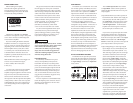
1) %JTDPOOFDUUIFTQFBLFSTGSPNUIF
BNQMJGJFSTiFront Speaker OutputswBOE
iRear Speaker OutputswDPOOFDUPST
2) Turn off all processing on the source
unit (bass/treble, loudness, EQ, etc.).
Set fader control to center position
and subwoofer level control to 3/4 of
maximum (if used to drive the 450/4v2).