


SYSTEM CONFIGURATION 17
To make this process as quick and as easy as pos-
sible, we suggest that you use the full-OSD sys-
tem with the on-screen menus, and step through
each input.
It is recommended that you record your settings
for each input using the work-sheets in the
appendix to this manual, in the event there is a
power loss or if you need to reenter the settings
for some other reason.
Input Setup
The first step in configuring the AVR is to select
an input, i.e. to associate an analog or digital
input with each input source in use, e.g. CD or
DVD. Note that once an input is selected, all
settings for the Digital Input, Speaker Configura-
tion, Delay and Surround Mode will ”attach”
themselves to that input and be stored in a
nonvolatile memory. This means that once made,
the selection of an input will automatically recall
those settings. For that reason, the procedures
described below must be repeated for each input
source so that you have the opportunity to
custom tailor each source to your specific
listening requirements. However, once made they
need not be changed again unless you need to
alter a setting.
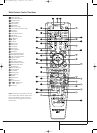
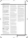
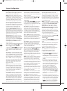
When using the full-OSD system to make the
setup adjustments, press the OSD button
L
once so that the MASTERMENU (Figure 1)
appears. Note that the
› cursor will be next to
the
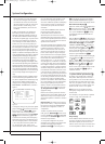
INPUTSETUP line. Press the Set button
F
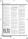
to enter the menu and the INPUT
SETUP
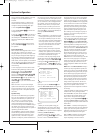
menu (Figure 2) will appear on the
screen. Press the
‹/› buttons
Ea
until the
desired input name appears in the highlighted
video, as well as being indicated in the front
panel Input Indicators
by the blue LED next
to the desired input name. If the input will use the
standard left/right analog inputs, no further
adjustment is needed.
Figure 2
The AVR offers you the option of renaming each
input (except tuner) as it appears in the on-screen
and front panel messages. This is helpful if you
have more than one VCR, if you wish to associate
a specific product brand name with the input, or
to simply enter any name that will help you to
remember which source is being selected.
To change the input name, press the
⁄
/
¤
Navigation Button
D
on the remote so that
the ➞ cursor is pointing to
NAME. Next, press
and hold the Set Button
F
for a few seconds
until a flashing box appears to the right of the
colon. Immediately release the Set Button
F
,
as you are now ready to enter the device name.
Press the
⁄
/
¤
Navigation Button
D
and
note that a complete set of alpha-numeric charac-
ters will appear with the start of the alphabet in
capital letters followed by the lower-case letters
and then numbers and symbols. When you press
the
¤
Navigation Button
D
, a series of sym-
bols and numbers will appear, followed by a
reverse list of the alphabet in lower-case letters.
Press the button either way until the first letter of
the desired name appears. If you wish to enter a
blank space as the first character, press the
›
Navigation Button
a
.
When the desired character appears, press the
›
Navigation Button
a
and repeat the process
for the next letter, and continue until the desired
name is entered, up to a maximum of fourteen
characters.
Press the Set Button
F
to enter the input
name into the system memory and to proceed
with the configuration process.
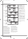
If your system includes any sources that are
equipped with Y/Pr/Pb component video outputs,
the AVR is able to switch them to send the proper
signals to your video display. Both Component
Video Inputs
JL
may be assigned to any
source for added system flexibility. The default
setting is for the Video 1 Component Video
Input
L
to be assigned to the DVD, with the
Component Video 2 Jacks
J
assigned to the
other inputs. If your system does not include com-
ponent video at this time, or if you do not need to
change these defaults, press the
¤
Navigation
Button
D
to go to the next setting.
To change the Component Video assignment, first
make certain that the ➞ cursor is pointing to the
COMPONENTIN line on the menu screen,
and then press the
‹
/
›
Navigation Button
Ea
until you see the desired input in the
highlighted video. The clicking noise that you will
hear when the component video inputs is
switched is normal, due to the relay used to
ensure proper isolation between the three inputs.
When the desired component input has been
selected, press the
¤
Navigation Button
D
go to the next setting.
If you wish to associate one of the digital inputs
with the selected input source, press the
¤
Button
D
on the remote while the INPUT
SETUP
menu (Figure 2) is on the screen, and
note that the on-screen cursor will drop down to
the
DIGITALIN line. Press the
‹
/
›
Buttons
Ea
until the name of the desired digital
input appears. To return to the Analog input,
press the buttons until the word
ANALOG
appears. When the correct input source appears,
press the
¤
button
D
until the ➝ cursor
appears next to BACKTOMASTERMENU,
and press the Set Button
F
.
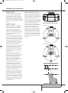
To associate an analog or digital input with the
input source currently selected at any time using
the discrete function buttons, press the Digital
Input Select Button
Û
G
on the front panel
or the remote while the full-OSD is not in use.
Within five seconds, make your input selection
using the Selector buttons on the front panel
7
or the
⁄
/
¤
D
Buttons on the remote until
the desired digital or analog input is shown in the
Main Information Display
Ò
and in the
lower third of the video display connected to the
AVR. Press the Set Button
F
to enter the new
input assignment.
Some digital video input sources, such as a cable
box or HDTV set-top may change between analog
and digital outputs, depending on which channel
is in use. The AVR’s Auto Polling feature allows
you to avoid losing the audio feed when this hap-
pens by permitting both analog and digital con-
nections to the same source on the AVR. Digital
audio is the default, and the unit will automati-
cally switch to the analog audio if the digital
audio stream stops.
In cases where only a digital source is used, you
may wish to disable the Auto Polling feature to
prevent the AVR from trying to “find” an analog
source when the digital source is paused.To turn
Auto Polling off for any input, first make certain
that the
➞ cursor is pointing to the AUTO
POLL
line on the menu screen. Next, press the
‹
/
›
Navigation Button
Ea
so that OFF
is highlighted in reverse video. Repeat the proce-
dure at any time by highlighting
ONto restore
the Auto Polling feature.
When DMP has been selected as the
source input, an additional line will appear in this
menu that lets you select whether you wish to
allow your iPod to continue charging while
docked in when the AVR 140 is turned
off and placed in Standby mode. To make your
selection, press the
⁄
/
¤
Buttons
D
until the
➞ cursor is next to the line reading
RECHARGEIN ST-BY. Press the
‹
/
›
Buttons
Ea
until the word YESappears if
you wish charging to continue, and the blue light-
ing on The Bridge will remain lit when the AVR
140 is in Standby mode to indicate that charging
is taking place. The default setting is
NO,in
which the docked iPod will not continue to charge
when the AVR 140 is turned off, even though
remains connected to the AVR.
When all needed adjustments have been made,
press the
¤
Button
D
until the ➞ cursor is
next to
BACKTOMASTERMENUto con-
tinue with the system configuration.
Surround Setup
The next step for that input is to set the surround
mode you wish to use with that input. Since sur-
round modes are a matter of personal taste, feel
free to select any mode you wish – you may
change it later.The Surround Mode chart on page
26 may help you select the mode best suited to
the input source selected. For example you may
select Dolby Pro Logic II or Logic 7 for most ana-
log inputs and Dolby Digital for inputs connected
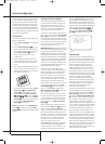
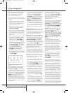
* INPUT SETUP *
INPUT :DVD
NAME:
COMPONENT IN:COMP V 1
DIGITAL IN:COAXIAL 1
AUTO POLL :OFF
BACK TO MASTER MENU
System Configuration
25339_AVR140_Eng_2 30/08/05 9:55 Side 17