


13
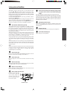
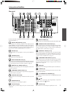
Index parts and facilities
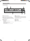
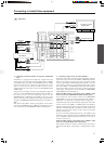
Rear panel
SURR
BACK/
ZONE 2
SPEAKERS
AUDIO
VIDEO
S VIDEO
MONITOR
OUT
IN
IN
IN
IN
IN
ZONE 2
DVD
VIDEO 1
VIDEO 2
VIDEO 3
VIDEO 4
AUDIO
VIDEO
S VIDEO
COMPONENT
VIDEO
Y
P
B
P
R
OUTPUT
INPUT 1
Y
P
B
P
R
INPUT 2
Y
P
B
P
R
FRONT SPEAKERS
L
RL
R
SURR SPEAKERS
CENTER
SPEAKER
R
L
R
L
PHONO
PRE OUT
FRONT
SUB
SURR
R
L
AUDIO
R
L
CD
TAPE
R
L
AUDIO
GND
SURR
BACK/
ZONE 2
IN
R
L
MULTI
CH
INPUT
FRONT
SUB
SURR
SURR
BACK
CENTER
R
L
R
L
AM
FM
75
I
R
IN
ZONE 2
REMOTE
CONTROL
A
B
RS232
12
V
TRIGGER OUT
AC
120
V 60
Hz
SWITCHED
TOTAL 120W 1A MAX.
AC OUTLETS
AV RECEIVER
MODEL NO.
DTR
-
7.3
AC
INLET
DIGITAL
INPUT
DIGITAL
OUTPUT
OPT
OPT
2
1
2
3
1
3
COAX
CENTER
ANTENNA
R
L
4 OHMS MIN. OR
6 OHMS MIN.
/SPEAKER
CAUTION
:
SPEAKER
IMPEDANCE
SEE INSTRUCTION
MANUAL FOR
CORRECT SETTINGS.
OUT
OUT
OUT
OUT
OUT
ETHERNET
[NET-TUNE]
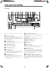
MULTI CH INPUT [27]
This connector is for connecting components with a multi-channel output.
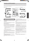
PHONO/CD/TAPE AUDIO IN/OUT [15]
These connectors are for connecting to the audio input and output
jacks on audio components. To connect a turntable, see page 17; to
connect a CD player, see page 17; and to connect a cassette tape
deck, MD recorder, or CD recorder, see page 17.
DVD/VIDEO1-4 IN/OUT [16-19]
These connectors are for connecting to the video input and output
jacks on video components. To connect a DVD player, see page 16;
to connect a DVD recorder, see page 18; to connect a VCR, see page
17; and to connect a satellite tuner, see page 19.
COMPONENT VIDEO INPUT1/2 [16, 18]
These connectors are for connecting to the component video outputs
of video components that have them. To connect a DVD player, see
page 16; to connect a DVD recorder, see page 18; and to connect a
satellite tuner, see page 19.
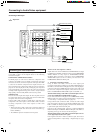
RS232 [26]
This connector is for connecting to the RS232 port of an external device.
IR IN/OUT [25]
These connectors are for connecting the remote sensor of a multi-
room kit (sold separately).
12V TRIGGER OUT A/B/ZONE 2 [27]
This connector is used to connect to the 12V TRIGGER IN terminal
of a component.
[26]
This jack is for connecting other Integra/Onkyo components
equipped with the same
terminal.
AC INLET [26]
This connector is for connecting the supplied power cord.
For more information regarding connection procedures, see pages
indicated in brackets [ ].
DIGITAL INPUT/OUTPUT [15-19]
These jacks are for connecting components with digital input and
output capabilities. To connect a CD player, see page 15; to connect an
MD or CD recorder, see page 15; to connect a DAT deck, see page 15;
to connect a DVD player, see page 16; to connect a DVD recorder, see
page 18; and to connect a digital satellite tuner, see page 19.
PRE OUT [27]
To use the DTR-7.3 as a preamplifier, connect a power amplifier to
this jack.
ANTENNA [22-23]
These jacks are for connecting a tuner.
ZONE2 AUDIO/VIDEO OUT [24]
These jacks are for connecting the components that will be used in the
remote zone (Zone 2). For more details on the connection procedures,
see “Connecting the remote zone (Zone 2) speakers” on page 24.
MONITOR OUT VIDEO/S VIDEO [17]
These jacks are for connecting to the video input jacks on television
monitors or projectors.
COMPONENT VIDEO OUTPUT [17]
These jacks are for connecting to the component video input jacks on
television monitors or projectors.
ETHERNET (NET-TUNE)
This connector is for connecting to an Ethernet network or personal
computer.
SPEAKERS [20-21]
These terminals are for connecting the speakers.
AC OUTLETS [26]
This AC outlet is provided to plug in the power cord from another
component.