


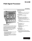
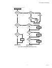
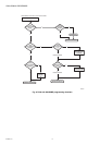
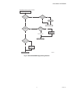
P520 SIGNAL PROCESSOR
9 66-2066—01
SETUP AND ADJUSTMENT
PROCEDURES
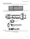
Sighting Adjustment
Before making definitive settings (i.e., establishing the set
points) for FLAME ON/OFF, the user must first optimize the
sighting of the viewing head. For detailed mounting and
sighting information, refer to the applicable literature for the
viewing head used.
Initial Setup
The initial settings for the P520 should be as follows:
1. F.F.R.T. (Time Delay Off) to 3 SEC.
2. GAIN SET to 25.
3. TIME DELAY ON to 0.
4. FLAME ON to 200.
5. FLAME OFF to 100.
6. IR GAIN to 451.
7. IR FILTER to 3 (33 Hz).
8. UV GAIN 32.
The above settings will be satisfactory for most applications,
but are used only as a starting point. Many variables can
affect the readings making it impossible to catalogue all the
settings, and each viewing head has its own characteristics for
the different types of fuels and burners.
The initial settings for viewing heads S509, S511, S512
should be as follows:
1. Set filter switch to LL position.
2. Gain potentiometers (POTS) full clockwise (these are
25-turn potentiometers – a slight clicking sound will be
heard when the POT is maximum clockwise). There are
two POTs on the S509: one for the Si channel, and one
for the PbS channel. If the fuel is natural gas, turn the Si
channel off (pot full counter clockwise).
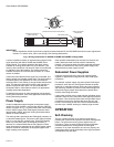
There are no initial settings for the S506 UV viewing head. It is
important that this viewing head be properly aimed to pick up
the maximum signal.
Adjusting Set Points
Before adjusting the set points, take readings with the P520
on the two following conditions; write down the readings for
the burner ON and OFF (with other burners on) under low
load conditions, and then the readings for the burner ON and
OFF under high load conditions.
There must be a definitive ratio between the readings for
burner ON and burner OFF. This ratio can be defined by using
the lowest reading for burner ON from both of the load
conditions, and the highest reading for burner OFF from both
of the load conditions. If the readings are 2:1 or more (BNR
ON to BNR OFF) then there should be no problem
discriminating between burners.
A good balance for the set points would be:
ON SET POINT = .75A + .25B
OFF SET POINT = .25A + .75B
where A is the lowest burner ON reading, and B is the highest
burner OFF reading.
A smaller ratio will work, as long as the lowest BNR ON
reading and the highest BNR OFF reading never deteriorates
to the point the former is equal to or less than the latter. In
other words, A must always be greater than B. Using a safety
factor of 2:1 will allow for flame signal changes that probably
will occur over different operating conditions.
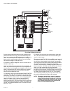
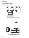
Viewing Head Temperature
The model S55XB/BE series of viewing heads have in place a
sensor for sensing the internal temperature of the head. To
access the reading of the viewing head temperature, press the
“Reset” and the “Down” arrow key at the same time. The
temperature reading will be displayed in the four-digit readout.
The reading (indicated in °C) will disappear and the normal
reading will continue after several seconds.