


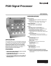
P520 SIGNAL PROCESSOR
66-2066—01 4
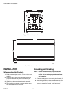
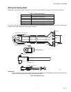
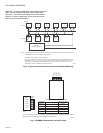
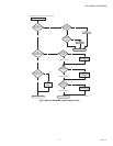
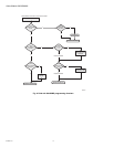
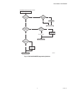
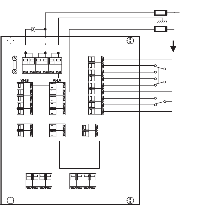
Fig. 3. Rear PCB terminal wiring.
Polarity must be observed when wiring this connection (the
positive terminal is on the top). This is an isolated input, so
two wires are required. Any DC voltage from 7.5 to 30 may be
used. The current required will depend upon the voltage,
because this is a photocoupler interface circuit with a 3900
ohm resistor feeding the LED light source.
For example: a 26VDC voltage will result in a current flow of
25/3900 =.0064 Amp.
If flame is being detected and the channels are switched, the
flame relay will remain energized for one cycle regardless of
the new set points, allowing channel changes “on the fly,” so to
speak. If the new flame OFF set point is equal to or greater
than the current signal count, then the flame relay will de-
energize on the subsequent cycle.
The remaining two-pin terminal designated REMOTE METER
(to the left of the V.H. SEL terminals) is for the remote meter
connection. This output is a current-driven signal that ranges
from 0 to 20mA for remote meters, and can be switched to a
range of 4 to 20mA (refer to section 4-20mA REMOTE
OUTPUT). Connect the terminal marked “positive” to the
positive meter terminal. This current signal can be used with a
volt meter by feeding the signal to a resistor connected to the
ground. The voltage developed across the resistor will follow
Ohm’s law V=IR.
For example: a 3-volt meter can be used with a resistor of 3/
.02 = 150 ohms, which will result in a full-scale reading of 3
volts for a 20mA output.
The terminals called TX+, TX-, RX+, and RX- (at the bottom of
the PCB) are used for the serial communication link. They are
also in pairs to accommodate “daisy chaining,” but the pairs
are arranged for twisted pairs instead of adjacent redundancy.
The serial communication is achieved by using ASCII
character code transmission at 4800 through the USB port on
the host computer. The P520 uses RS-422 data transmission
which is over two, twisted pairs that are differentially
transmitted and received, allowing long wire runs to be used
through noisy environments. A USB to RS422 converter must
be used to communicate with the P520, and the connections
are made to the terminals marked TX+, TX-, RX+ and RX-.
The transmitting, twisted pair goes to the TX terminals, and
the receiving, twisted pair goes to the RX terminals.
NOTE: The terms “transmit” and “receive” used here
with respect to the P520 will be reversed with
respect to the converter connection on the host
computer. Refer to later sections in this manual
for a detailed description of the software and
how it is to be used with the P520.
P520
F1/.75A
M33217
F2/.25A
P520
RELAYS
FLAME RELAY
RF
RF
RC
SELF
CHECKING
RELAY
PWR IN
BAT
+26VDC
GND
RF C
OFF
ON
ON
OFF
RF C
ON
OFF
RC C
GND
+V
SC
SIG
SIG
GND
+
GND
REMOTE METER V.H. SEL
CHAN SEL
TX+ TX- TX+ TX-
RX- RX+ RX- RX+