


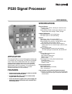

P520 SIGNAL PROCESSOR
5 66-2066—01
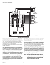
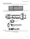
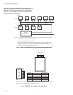
Wiring the Viewing Head
Wiring of the viewing head is made to the terminals on the rear backplane PCB. These terminals are described as follows:
Fig. 4 and 5 show four-conductor cable to the viewing head. Note that the flame signal wire going to terminal SIG is shielded, and
the shield is terminated at both ends of the cable to SIG GND.
IMPORTANT
Source impedance resistor required at the signal processor between SC and SIG GND terminals for proper signal trans-
mission. For resistor value, refer to Wiring of Viewing Head section.
Fig. 4. Viewing head wiring.
Table 1. Terminal Descriptions.
Terminal Description
+V 24VDC power to viewing head
GND Power Ground
SC Self-check/shutter drive signal to viewing head
SIG Flame signal from viewing head
SIG GND Signal ground
M33509
CABLE CLAMP
CONNECTOR WITH
REAR COVER REMOVED
CONNECTOR
JACKSCREW
FINAL ASSEMBLY
OPTIONAL LTA5XX ADAPTER
CONNECT SHIELD
TO TERM 3
USE SHRINK TUBING
WIRING SIDE VIEW – COVER REMOVED
P520
RED
GREEN
BLACK
WHITE
SHIELD
C20
C28
A24
A26
A28
+24 VDC
GND
SHUTTER
DRIVE
GND
SIGNAL
R
4
3
2
1
5
G
W
B