


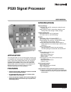

P520 SIGNAL PROCESSOR
66-2066—01 10
TROUBLESHOOTING
Module Communications
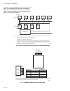
The P520 communicates with any host computer that has a
USB port and supports ASCII character code transmission at
4800 baud (or, in current revisions of the processor chip, at
4800 or 9600 baud). The baud rate is displayed with the
module address in the current versions (see SETTING
ADDRESSES, section). The data transmitted to and from the
P520 is over two twisted pairs that are differentially driven and
received according to the RS-422 standard. The differential
mode allows long wire runs in harsh, electrical environments.
Honeywell offers a RS485/422 to USB converter to use in
conjunction with the P520 signal processor. The Honeywell
part number is COMMOD.
Modbus Communication protocol allows the P520 to
communicate with open process controllers or human-
interface host computers that support this protocol. The P520
processor status and settings are organized as 23 4X holding
registers and five 0X discrete registers. For more information
on Modbus protocol, please refer to Modicon’s Modbus
Protocol Reference Guide (PI-MBUS-300 Rev E).
Communication Setting
P520 can communicate only in Modbus RTU mode, with the
following configuration:
• 9600 baud
• 8 data bits
• No parity
• 1 stop bit
The factory default of a P520 station number is 0. It is
important to change the station number so that there are no
duplicate stations in the network.
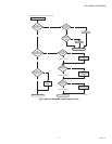
Table 5. Troubleshooting procedures.
Problem Troubleshooting Steps
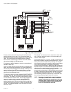
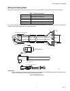
No flame signal and no display. 1. Check the wiring between the signal processor and the viewing
head. Refer to the Wiring the Rear PC Board section.
2. Using a volt meter check the voltage at PWR IN terminals with a
volt meter. It should measure approximately 24VDC. If not,
check the power supply and wiring, or replace the power supply.
3. If 24VDC is measured, remove the power for 10 seconds. If the
self-resetting fuse has tripped, removing then reapplying power
will reset the fuse.
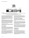
Digital display shows 0000 and there is no flame signal. 1. Remove connector from viewing head and check wiring per
Fig. 4 and 5.
2. Ensure the proper impedance resistor is in place (refer to Wiring
of Viewing Head section). Using a volt meter, check the viewing
head terminals on the P520, for 24VDC across +V and GND. If
the voltage is low, check input voltage to the signal processor. If
the input voltage is measured to be in spec, remove power and
disconnect all connections to the viewing head(s). Wait 10 sec-
onds (which resets the self-resetting fuse) and then reapply
power and re-measure voltage across +V and GND.
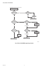
3. If voltage measures +24VDC (nominal) at the viewing head ter-
minals at the signal processor, turn off power to the signal pro-
cessor and using an ohmmeter check continuity of each cable
wire from the signal processor terminals to the viewing head
connector terminals. If cable continuity checks out, the viewing
head may be defective.
Flame signal shows on display; flame on relay and light
are off.
1. The viewing head is incorrectly wired, or defective (see above).
2. The set point values for flame ON are incorrect.
Flame signal shows on analog bar graph display; flame
light is off; lockout light is on.
1. The viewing head may be defective.
2. There may be a noise or grounding problem. Check that equip-
ment is properly grounded and ensure good clean contact on all
ground connections. Move viewing head and cable/conduit at
least 12 inches (31 cm) away from any source of high powered
switching (e.g. igniter equipment). Refer to Grounding and
Shielding section.
3. Press the RESET button on the front panel.
The 1-9 LED stays on. 1. There may be a noise or grounding problem (see above and
refer to Grounding and Shielding section).).
2. The viewing head may be defective.
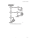
The front panel buttons do not respond. 1. The P520 front panel may be locked out.
2. Signal processor may be in remote operation only mode.
3. Cycle power to the signal processor with the viewing head con-
nected.