


P520 SIGNAL PROCESSOR
3 66-2066—01
3. Install a ground wire from the ignition transformer case
to the igniter assembly.
4. Ensure all igniter wires and cables show no signs of
wear. Replace any igniter cables or wires that are frayed
or cracked.
5. The viewing head must be electrically isolated from the
burner front.
a. Electrical isolation can be accomplished by install-
ing an Ultem nipple or an Ultem locking coupler
adapter in conjunction with a locking coupler
between the viewing head flange and the burner
mount.
b. The purge air line should also be isolated from the
viewing head. This can be accomplished by install-
ing any insulating material, for example a rubber
hose, in between the purge air line and the viewing
head.
6. On the terminals going to the viewing heads on the back
of the P520, the terminals marked GND go to pin 5 of
the S5XX and S55XB viewing head plug and to the des-
ignated ground pin for the S55XBE viewing head plug.
Pin 5 of the S5XX and S55XB and the ground pin for the
S55XBE viewing head male receptacles have an inter-
nal tab that grounds this connection to the viewing head
housing. The terminal marked GND connects to the
chassis ground of the P520. This ground is made
through the internal PCB to the metal base of the P520.
It is important that good grounding practices be followed when
connecting power supplies. Interference problems can occur if
the power supply chassis and the P520 chassis are at a
different ground potential than the viewing head housing,
which will be at a ground potential associated with the burner
front. In these situations, the Honeywell viewing head
effectively supplies a plant ground between the burner front
and the panel enclosure. If there is a large potential difference
between these points, considerable current can flow through
the viewing head cable, which can, in turn, damage the P520
signal processor or the associated power supply.
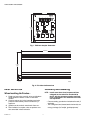
Card Frames
Four card guides are required for each P520 module;
therefore, a total of sixteen card guides would be required to
mount four P520 modules. Card guides are available as off
the shelf parts and are not available from Honeywell.
The resulting rack will require spacers for the top and bottom
of the rear backplane PCB. Card guides are required as well
for installation. Spacers and card guides are available from
electronic vendors and are not available from Honeywell.
A half-card frame, or “half rack” (9.5 inches wide) may be used
as an alternative to the 19-inch card frame. A half rack will
mount two P520 modules.
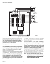
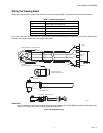
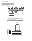
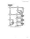
Wiring the Rear PC Board
A diagram of the rear backplane circuit board is shown in Fig.
1. The relay outputs are located on the nine-contact terminal
block located on the upper right of the board
RC C refers to the common terminal of the self-checking relay.
There is only one pair of contacts used for the self-checking
function. Here, the designation ON refers to the self-checking
taking place in a normal manner. OFF indicates a failure in the
viewing head or processor resulting from
- the internal or external hardware
- electronic critical component failure
- the power to the unit is OFF – the most likely condition
The horizontal set of six terminals (top left) is used for the
main power into this plug-in module (PWR IN). Each
designated terminal is a double terminal, or pair, so that the
wiring from the power supply can be “daisy chained” from one
P520 to the next without having to twist wires together into
one termination.
The pair designated BAT is for battery backup, if used. The
backup battery, if used, should be 24 volts, to ensure that the
24VDC power feeding the P520 will not feed back into the
battery. In other words, no current will flow from the battery as
long as voltage of the main power supply is above that of the
battery. The negative side of the battery goes to the GND
terminal on the right.
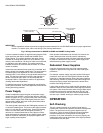
Fig. 1 shows how these terminals are connected inside the
P520. Note the two fuses marked F1 and F2. F1 is the main
power fuse for the signal processor as well as the viewing
head(s), and is rated at .75 Amp. Fuse F2 feeds only to the
viewing head(s), and is rated at .25 Amp. Each viewing head
draws about 100mA, so this output can supply up to two
viewing heads. On all currently manufactured units, these
fuses are self-resetting types, and will recover from an
overload automatically after power is removed from the P520
for 10 seconds.
Just below the six-pin PWR IN terminals are two, five-pin
vertically-mounted viewing head terminals identified as V.H. A.
and V.H. B. If only one viewing head is used, you must wire to
the V.H. A. terminals. Below the V.H. A. terminals are two
terminals marked V.H. SEL (viewing head selector relay).
Energizing this connection with 24VDC will cause the relay on
this PCB to switch to viewing head B.
Only the viewing head signal wire (SIG) and the signal ground
wire (SIG GND) are switched with this changeover relay; the
24VDC and power ground circuit is not disturbed. Make sure
that the viewing head signal wire and signal ground (braided
shield in the four-conductor cable) are both connected,
because this ground connection is the only return path for the
signal and self-checking circuit. The 24VDC used to switch
this relay can be connected without regard to polarity. The two
terminals marked V.H. SEL go directly to the relay coil.
The two-pin terminal to the right of V.H. SEL designated
CHAN SEL is used for selecting channel A or channel B on
the P520. Energizing this pair of terminals causes the B
channel to be selected.