


P520 SIGNAL PROCESSOR
66-2066—01 6
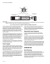
IMPORTANT
Source impedance resistor required at the signal processor between SC and SIG GND terminals for proper signal trans-
mission. For resistor value, refer to the Wiring of the Viewing Head section.
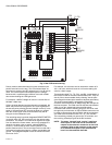
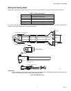
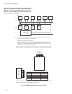
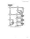
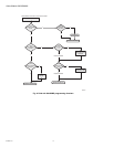
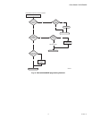
Fig. 5. Wiring connections for S550BE, S552BE and S556BE viewing heads.
A source impedance resistor is required when using the P520
signal processor with S55X, S55XB and S55XBE series
viewing heads. This resistor should be 330 ohms (factory
installed) for viewing head cable runs up to 500 feet (152
meters), and it should be 150 ohms for cable runs of 500 feet
to 1000 feet (152 to 305 meters). The resistor should be
installed across the SC and SIG GND terminals. A 1/4 watt
resistor is suitable.
It should be noted that the flame signal wire is shielded, and
that the shield is terminated at both ends. The shield must be
a braided type for this application in order to maintain an
electrical path. For this reason, a foil type shield should not be
used. This signal ground shield is also the self-checking or
shutter drive circuit return path. It is recommended that
Honeywell C328 or C330 cable be used for all applications
(viewing head model dependent).
For detailed instructions on cable preparation and wiring the
viewing head connector, refer to the applicable manual for the
viewing head being installed.
Power Supply
Careful consideration should be given to the power supply
used for the P520. 24VDC is used to back bias the “steering”
rectifier, as shown in Fig. 3, to prevent the power from feeding
into the 24VDC supply. Each P520 signal processor draws
approximately 150mA, and each viewing head draws about
100mA of current (24VDC).
The viewing head is powered by the P520 signal processor via
a 0.25A self-resetting fuse. The power to the signal processor
itself is via a 0.75A self- resetting fuse. These self-resetting
fuses are re-set when power to the signal processor is
removed. It is recommended that no more than four P520
signal processors be supported by one 24VDC power supply,
unless a method of redundancy is employed together with
larger capacity power supplies.
Other possible combinations can be used; for instance, the
battery backup terminal could be used for redundancy.
However, care must be taken with these redundant schemes
to make sure that failure of the primary power supply won’t
affect the backup power supply, as well.
Redundant Power Supplies
It may be more economical to use larger-capacity power
supplies for applications using twelve or more P520 signal
processors.
For example: a power supply may power twelve P520 signal
processors, each with one viewing head. Should the power
supply fail, a redundant scheme utilizing two power supplies
with “steering” rectifiers to prevent current from flowing into a
failed power supply output would prevent the twelve flame
monitors from being shut down.
Larger power supplies can be used with this redundant wiring
scheme if there are more than twelve P520 signal processors
in a system. Care should be taken when wiring multiple signal
processors to ensure the selected bus wires will carry the
current. The terminals on the rear PCB will accommodate a
wire size up to 14AWG, allowing for relatively high currents.
OPERATION
Self-Checking
There is a small processor in all viewing heads and it is
possible that it could fail and produce erroneous viewing head
pulses. The self-check circuitry guards against such an
occurrence. There are several tasks that require intelligent
interaction between the viewing heads and the signal
processor. If all of the interactions do not occur properly, the
viewing head will not send pulses back to the signal processor
and the flame relay will open.
CABLE PN: C328
RED
WHITE
GREEN
BLACK
SHIELD
SIG
SC
+V
GND
SIG
GND
BLACK
RED
CONNECTOR BACK WIRING VIEW (FEMALE)
SIGNAL PROCESSOR
CONNECTION
M33281
SHIELD
GREEN
WHITE
USE SHRINK TUBING
CONNECTOR PROTECTOR
SLEEVE (SUPPLIED)