


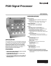
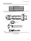

P520 SIGNAL PROCESSOR
7 66-2066—01
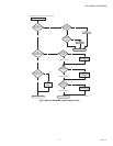
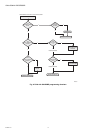
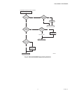
Verifying the validity of the gain code received is one of the
tasks performed by the processor in the viewing heads. The
self-check pulse from the signal processors is a 100ms-wide,
20V to 24V pulse with two notches or breaks in it. The position
of each of the two notches communicates a gain code one to
nine plus parity to the viewing head. The viewing head sends
back an ID pulse in the first half of the 100ms self-check time.
One viewing head expects to receive data with one parity and
the other expects to receive data with the other parity. If a
viewing head does not receive its correct parity plus the gain
code once per second, it produces no output pulses.
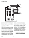
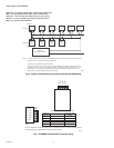
Powering up the P520
Once the power is connected (24VDC) to the proper terminal,
the P520 signal processor will be operational. There is no ON/
OFF switch on the P520; the moment it is powered on, it will
reset and initialize. The self-checking light will start flashing,
and one of the channel LEDs (A or B) will light (A will be ON if
the channel select input at the plug-in connector is de-
energized). Ensure that the voltage is 24 to 26VDC. The P520
signal processor will be reset when the power is turned on.
The P520 has been designed to deal with any foreseeable
power failure or anomaly.
For example: if the power goes off while you are in the
process of storing a set point (either from the front panel or
from the remote, host computer), the internal power monitor
circuit will signal the P520 signal processor to complete the
store function before shutting down in an orderly manner. This
prevents invalid data from being stored and protects existing
data in the EEPROM (Electrically Erasable Programmable
Read Only Memory) from corruption. This shut down process
is facilitated by a special internal power supply that provides
power just long enough to allow the processor to perform the
shut down.
This internal circuit monitors the 24VDC power feeding the
P520 signal processor, and when the voltage drops to about
19 volts, the processor shuts down, the program stops
running, and the self-checking function ceases (the self-
checking relay de-energizes). The blinking, SELF-CHECK
O.K. light on the front panel will go out, and the flame relay will
de-energize.
Note that the earlier S509 and S512 viewing heads will shut
down at about 17.0 volts; these viewing heads have their own
power-monitoring capability, and will shut down on their own,
independent of the signal processor.
When the power feeding the P520 exceeds 19 volts, the
program is re-started. The SELF-CHECK O.K. light will start
blinking, and the self-check relay will energize. If flame is
present and a S509 or S512 viewing head is being used, the
flame signal will not come back on until the power reaches
21.5 volts. This can cause a lockout condition if the viewing
head turns on during the dark period (defined by the periodic
self-check signal going to the viewing head each second),
requiring a manual reset of the P520. There is a 20 per cent
probability that a lockout will occur because of the duty cycle
of the self-check function (200 mSEC on and 800 mSEC off).
The S506 and S511 do not incorporate the power-monitoring
shutdown function, and will not cause a lockout condition.
These design precautions ensure that there will never be an
unsafe situation created by abnormal line power (115VAC)
conditions. The 26VDC power is very unlikely to come on
gradually, but, if this did occur, the P520 would not get a
proper reset. So, there is another function in the micro-
processor (used in the P520), implemented by circuitry and
software, that causes the P520 to appear dead (i.e., the front
panel will be dark) and to stay this way until the power is
recycled in an abrupt manner, initiating the reset.
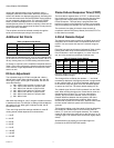
Set Points
There are 16 set points stored in memory in the P520, divided
into two equal sets, A and B. The 5 items listed in Table 2 can
be accessed directly from the buttons on the face of the signal
processor per the instructions below.
To review any of the currently stored set points for the 5 items
above, push the related button on front of the P522. For
instance, to determine the current FLAME ON set point, press
the FLAME ON button. The set point will be displayed on the
readout for about four seconds, then the display will return to
normal. The set points displayed will be for the channel that is
active, which is indicated by a steady illumination of push-
button A or B.
To review the set points for the other channel, first select the
channel (A or B), then press the related set point button.
For example: if channel A is already ON, indicating it is
functional, and B is pressed, A will go out and B will proceed
to flash slowly, indicating that further action is required. If A is
already ON and A is pressed, it will stay steady ON and start
to blink rapidly after any of the five set point buttons listed
above are pressed.
In all cases, A or B will rapidly blink after the set point is
selected. This action serves to alert the user that the current
display is no longer that of the flame signal, and further action
is required.
The fact that A or B is already on has nothing to do with the
process of viewing the current set points, except that you do
not have to select the channel if it is already on. The steady
illumination of A or B indicates which channel is functionally
active, and is selected at the terminals marked CHAN SEL.
At any time, you can press the reset button causing the P520
signal processor to return to normal operation. The reset
button is also used for resetting the lockout condition as
explained in the section Self-checking Function.
Additionally, the viewing head temperature can be viewed by
pressing the reset and down arrow button simultaneously.
Changing Set Points
Changing any of the five set points shown in Table 2 can be
accomplished by selecting the set point via its button on the
control face and using the UP or DOWN arrow buttons to
Table 2. Set Point types.
Set Point Display Number
FLAME ON 4 DIGIT NUMBER 0001-2999
FLAME OFF 4 DIGIT NUMBER 0000-2999
GAIN SET 2 DIGIT NUMBER 00-99
F.F.R.T. 1 DIGIT NUMBER 1, 2 OR 3
TIME DELAY ON 1 DIGIT NUMBER 0,1, 2 OR 3