


P520 SIGNAL PROCESSOR
66-2066—01 2
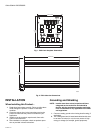
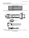
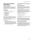
Fig. 1. P520 front faceplate dimensions.
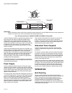
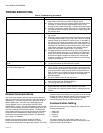
Fig. 2. P520 side view dimensions.
INSTALLATION
When Installing this Product…
1. Read these instructions carefully. Failure to follow them
could damage the product or cause a hazardous
condition.
2. Check the ratings given in the instructions and on the
product to make sure the product is suitable for your
application.
3. Installer must be a trained, experienced, flame safe-
guard control technician.
4. After installation is complete, check out product opera-
tion as provided in these instructions.
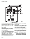
Grounding and Shielding
NOTE: Installer must be a trained, experienced flame
safeguard service technician and should be
familiar with the equipment operation and limita-
tions and be aware of any applicable local codes
and regulations.
1. Connect a safety ground to the viewing head housing (if
applicable).
2. The viewing head and all associated cable/conduit must
be at least 12 inches (31 cm) from any source of high
energy or voltage (for example, igniter equipment).
M33219
4-3/16 (106)
5-1/16
(129)
M33226
9-3/32 (231)
5-1/16
(129)
35/64
(14)