


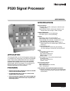


P520 SIGNAL PROCESSOR
11 66-2066—01
To change or check the station number of the P520, proceed
as follows:
1. Press and hold the Reset button for 4 seconds.
2. The 4 LED digits will show the baud rate and the station
number. The 2 leftmost digits are the baud rate (96 or
48); the 2 rightmost digits are station number from (0 to
63).
3. Press the up/down button to change the station number.
4. Press the Store button to save station number.
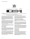
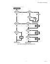
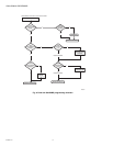
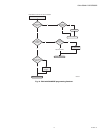
Protocol Detect
P520 with firmware version 5.0 still supports the existing
Honeywell proprietary protocol. After power-up, the processor
will listen for both protocols. Once the protocol has been
detected, communication must remain in this protocol until the
unit is powered off.
MODBUS RTU Function Supported
Four Modbus functions are supported:
• 01 Output Coil Read
• 03 Holding Register Read
• 06 Preset Single Holding Register
• 16 Preset Multiple Holding Register
Registers Map
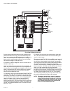
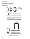
Communication with Modicon PLC
Each Modicon PLC comes with a Modbus port. The control
program can read/write the settings from/to the P520 signal
processor via this port. A XMIT loadable module is needed to
send Modicon functions. The XMIT loadable module is
available from Modicon Inc.
NOTE: Not all models of Modicon PLC’s will accept the
XMIT loadable module. Please consult your local
Modicon dealer for more information.
Communication with Human-
Interface Host Computer
A number of Modbus drivers for your operating system are
available from third party developers. These drivers allows
your application programs to communicate with the P520
signal processors directly.
USB to RS-422 Conversion
It is necessary to use a converter at the host computer. The
Honeywell COMMOD converter module can be used, and is
recommended because of its photocoupler isolation. The
converter must have galvanic ground isolation.
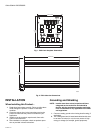
Setting Addresses
Each P520 must have its own unique address. The address
can easily be changed by pressing the RESET push-button for
>2 seconds. This causes the P520 to display its address on
the four-digit display (0000 to 0063). The address can now be
changed by using the UP or DOWN arrow buttons. When the
desired address is displayed, push the STORE button, and the
P520 will restore this new address.
In P520 signal processors with software revision 3.p and
higher, the baud rate can also be changed when the module
address is changed. The baud rate is displayed in the highest
two digits of the numeric display (i.e., 4802 is 4800 baud and
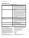
Table 6. 4x or numerical registers.
Value Definition
400001 Flame Count Of Active Channel (read
only)
400002 Processor Status (read only)
400002/0 Viewing head/Channel Selected
(0=Channel A)
400002/1 Flame On Relay Status
400002/2 Processor Lockout Status (0=lockout)
400002/3 Panel Access Disabled (0=disabled)
400002/44-20 Output Status (0=0-20)
400003 Flame On Channel A
400004 Flame On Channel B
400005 Flame Off Channel A
400006 Flame Off Channel B
400007 Gain Channel A
400008 Gain Channel B
400009IR Analog Gain Channel A
400010IR Digital Gain Channel A
400011IR Filter Channel A
400012UV Gain Channel A
400013IR Analog Gain Channel B
400014IR Digital Gain Channel B
400015IR Filter Channel B
400016UV Gain Channel B
400017 Viewing Head Type Channel A (read
only)
400018 Viewing Head Type Channel B (read
only)
400019 Temperature Channel A (read only)
400020 Temperature Channel B (read only)
400021 Time Delay on (Upper nibble = B lower
=A)
400022FFRT (Upper nibble = B lower = A)
400023 Firmware Version # (read only)
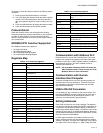
Table 7. 0x or discrete registers (all read only).
Value Definition
000001 Viewing head/Channel Selected
(0=Channel A)
000002 Flame On Relay Status
000003 Processor Lockout Status (0=lockout)
000004 Panel Access Disabled (0=disabled)
0000054-20 Output Status (0=0-40)
Table 6. 4x or numerical registers.
Value Definition