Bendix/King
KMA28
Audio Amplifier/Intercom/Marker Beacon Receiver
006-10565-0000 Page 1-1 Rev. 0, Sept. 2000
Section I GENERAL INFORMATION
1.1 INTRODUCTION
The KMA 28 represents the next step in cockpit audio control and intercommunications.
Using proprietary IntelliVox® design, this unit eliminates the requirements for intercom
squelch adjustments. The unit is designed for outstanding ergonomics and visually de-
fined mode annunciation and selection.
Before installing and/or using this product, please read this manual completely. This will
ensure that you will take full advantage of all the advanced features in the KMA 28.
1.2 SCOPE
This manual provides detailed installation and operation instructions for the Honeywell,
Inc. KMA 28 Audio Selector Panel/Intercom System
Model Description Part Number
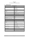
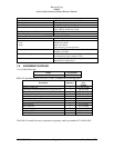
KMA 28 Stereo Audio Panel with Marker 066-01176-0101
1.3 EQUIPMENT DESCRIPTION
The KMA 28 is a state of the art audio isolation amplifier and audio selector that contains
an automatic voice activated (VOX) intercom system. It can switch up to three transceiv-
ers (Com 1, Com 2 and Com 3) and six receivers (Nav 1, Nav 2, ADF, DME, MKR and
AUX).
The TEL mode allows the KMA 28 to act as an audio interface between aircraft head-
phone and microphones and specific aircraft approved (FAA/FCC) cellular telephone
equipment.
Warning
: Use of non-aviation approved cellular telephone equipment may be prohibited by regulation.
Honeywell, Inc. is not responsible for unauthorized airborne use of cellular telephones.
There are two unswitched inputs, for autopilot disconnect, and/or radar altimeter warning.
Push buttons select the receiver audio source provided to the headphones. A SPR button
allows the user to listen to the receiver(s) selected on the cabin speaker. Except for the
unswitched inputs, all speaker audio is muted during transmit.
A rotary switch selects one of the three communication transceivers for the pilot and co-
pilot position, and allows radio transmission. In "Split Mode" the KMA 28 has the ability
to allow the pilot and copilot to operate different transceivers independently. The TEL
mode allows the pilot to use the cellular telephone interface. External switches permit
telephone operation for the copilot and passengers.
An emergency mode connects the pilot headphone and microphone to COM 1 if power is
removed for any reason, or if the power switch is placed in the Off (emergency ) position.
I
ntelliVox® is a trademark of PS Engineering, Incorporated, and used with their permission


