


Bendix/King
KMA28
Audio Amplifier/Intercom/Marker Beacon Receiver
006-10565-0000
3-7 Rev. 0, Sept. 00
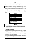
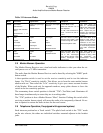
Table 3-1 Intercom Modes
Mode Pilot Hears Copilot Hears Passenger Hears Telephone Comments
Isolate
A/C Radios
Pilot Sidetone
(during radio transmis-
sion)
Entertainment 1 is
Muted
Copilot and passenger
intercom
Entertainment #1
Passenger and Copilot
intercom
Entertainment #2
“Phone Booth” mode
Pilot has exclusive use of
the telephone.
In TEL, Pilot connected to
Com 1 for PTT TX and re-
ceive.
This mode allows the
pilot to communicate
without the others both-
ered by the conversa-
tions. Copilot and pas-
sengers can continue to
communicate and listen
to music
All
Pilot
Copilot
A/C Radio
Passengers
Entertainment #1
Copilot
Pilot
A/C Radio
Passengers
Entertainment #1
Passengers
Pilot
Copilot
A/C Radio
Entertainment #2
All have access to phone
through Hook Switch. Pilot
access through TEL switch.
All hear telephone audio.
This mode allows all on
board to hear radio re-
ception as well as com-
municate on the inter-
com. Music and intercom
is muted during intercom
and radio communica-
tions
Crew
Pilot
Copilot
A/C Radio
Entertainment #1
Copilot
Pilot
A/C Radio
Entertainment #1
Passengers
Entertainment #2
Pilot and copilot don’t have
phone access, unless mic
sel in TEL. Passengers
have phone through Hook
Switch, Passengers hear
phone audio.
This mode allows the
pilot and copilot to con-
centrate on flying, while
the passengers can
communicate amongst
themselves.
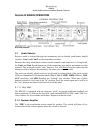
3.5 Marker Beacon Operation
The Marker Beacon Receiver uses visual and audio indicators to alert you when the air-
craft passes over a 75 MHz transmitter.
The audio from the Marker Beacon Receiver can be heard by selecting the "MKR" push-
button switch.
A three-position switch is used to set the receiver sensitivity and to test the indicator
lamps. Use "HIGH" sensitivity initially. This allows you to hear the outer marker beacon
about a mile out. Then select the “L
OW” sensitivity to give you a more accurate location
of the Marker. When used only for approach markers, many pilots choose to leave the
switch in the low sensitivity position.
The momentary down switch position is labeled "T/M" (Test/Mute) and illuminates all
three lamps simultaneously to assure they are in working order.
The “T/M” position is also a Marker Beacon “Mute” function. Pushing this switch while
receiving a marker beacon signal will cause the audio to be temporarily silenced. No ac-
tion is required to restore the audio in time for the next beacon.
3.6 Telephone Operation (if equipped with approved system)
Each intercom position has a "hook switch." The pilot's hook switch is the "TEL" mode
on the mic selector, the others are individual switches mounted adjacent to the headset
jacks.