


006-10565-0000 Appendix D Rev. 0, Sept. 2000
Appendix D- Instructions for FAA Form 337 and Continuing
Airworthiness
7.1 Instructions for FAA Form 337
One method of airworthiness approval is through an FAA Form 337, Major Repair and Alteration (Air-
frame, Powerplant, Propeller, or Appliance) In the case of the KMA 28, you may use the following text as
a guide.
Installed audio selector and 6-place intercom, Honeywell KMA 28, part number 066-01176-
(XXXX) in ( location ) at station .
Installed per AC43.13-2, Chapter 2, paragraph 23 (In-
strument Panel Mounting). Installed per Honeywell Installation Operators Manual p/n 006-10565-
(____), revision (), dated ( ).
This unit is FAA-Approved under TSO C50c for audio amplifiers, TSO C35d for Marker Beacon
Receivers, and meets appropriate environmental qualifications outlined in RTCA DO-160B as ap-
propriate or this aircraft.
Interface to existing aircraft radios in accordance with installation manual and in compliance with
practices listed in AC43.13-2, Chapter 2. All wires are Mil-Spec 22759 or 27500. Connection to
aircraft dimmer bus is ____________________. Power is supplied to the unit through a __A cir-
cuit breaker (type and part number), and total electrical load does not exceed
% of the elec-
trical system capacity with the KMA 28 added.
Aircraft equipment list, weights and balance amended. Compass compensation checked. A copy of
the operation instructions, contained in Honeywell document 006-10565-(____), revision ( ), dated
( ), is placed in the aircraft records. All work accomplished listed on Work Order .
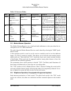
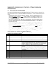
Instructions for Continuing Airworthiness,
Sample ICA Checklist for KMA28:
Section Item Information
1 Introduction Installation of audio control panel with integrated marker beacon receiver and
intercommunications system.
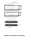
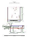
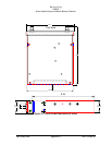
2 Description Installation as described in manufacturer’s installation manual referenced on
FAA Form 337, including interface with other avionics audio as required.
3 Controls See installation and operator’s guide referenced on FAA Form 337.
4 Servicing None Required
5 Maintenance Instructions On Condition, no special instructions
6 Troubleshooting In the event of a unit problem, place the unit into “OFF/EMG” mode. This
allows pilot communications using COM 1. Follow checkout instructions in the
installation manual referenced on the FAA Form 337. For a specific unit fault,
contact the manufacturer at 1-800-257-0726 for special instructions.
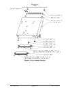
7 Removal and replacement informa-
tion
Removal: Using a 3/32” Allen-head wrench, carefully unscrew the locking
screw located in the center of the unit. While turning the wrench CCW, gently
pull on the EDGES of the bezel until the unit is free from the mounting tray.
Installation: Engage the locking screw at the back. Turn the locking screw CW,
while applying slight pressure to the edges of the bezel. Do not over tighten!
8 Diagrams Not applicable
9 Special Inspection Requirements Not Applicable
10 Protective Treatments Not Applicable
11 Structural Data Not Applicable
12 Special Tools None
13 Not Applicable Not Applicable
14 Recommended Overhaul Periods None
15 Airworthiness Limitations Not Applicable
16 Revision To be determined by installer