


Bendix/King
KMA28
Audio Amplifier/Intercom/Marker Beacon Receiver
006-10565-0000 Page 2-7 Rev. 0, Sept. 2000
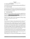
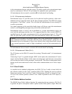
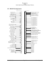
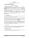
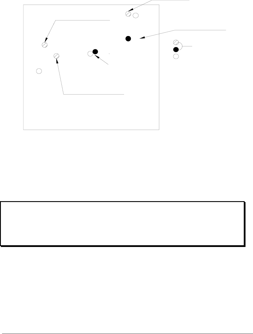
2.6 Adjustments
The KMA 28 is factory adjusted to accommodate the typical requirements for most air-
craft configurations. There are five adjustments however, that will allow the installer to
tailor the specific functions.
Marker Gain
CW- Reduce
Passenger Volume
CCW Increases
Marker Audio
CW Decrease Volume
MKR Low Sense
CW Decrease Sens.
Front of Unit
KMA28 adjustment holes
Not used
Speaker Volume
CW-Increase
211
231
223
133
111
Figure 2-1- KMA 28 Adjustments
2.7 Communications Antenna Installation Notes
For best results while in Split Mode, it is suggested that the one VHF communications
antenna is located on top of the aircraft while the other communications antenna is in-
stalled on the bottom. Any antenna relocation must be accomplished in accordance with
AC 43.13-2A, aircraft manufacturers’ recommendations and FAA-approved technical
data.
Warning:
It is probable that radio interference will occur in the split mode when the frequencies
of the two aircraft radios are adjacent, and/or the antennas are physically close to-
gether. Honeywell makes no expressed or implied warranties regarding the suitability
of the KMA 28 in Split Mode.
2.8 Wireless telecommunications interface
The KMA 28 has interface capability with units such as the AirCell units. It is the user’s
responsibility to determine the appropriate legal use of the equiment, and provide the
services.
Interface to the AirCell unit is through J1 (bottom) connector, pins 14 and N. Pin 14, la-
beled cellphone ring, is connected to pin V of the 3100D J3 connector and pin N of J1 is