


Bendix/King
KMA28
Audio Amplifier/Intercom/Marker Beacon Receiver
006-10565-0000 Page 2-2 Rev. 0, Sept. 2000
2.3.3 Mounting Rack Installation
Set the unit aside in a safe location until needed. Install the tray using six FHP 6-32 x ½"
screws. The audio selector panel must be supported at front and rear of the mounting tray.
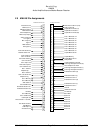
2.3.4 Connector Assembly
The unit connectors mate directly with the circuit boards in the KMA 28. The connectors
are a Molex crimp-type, and require the use of a Molex hand crimp tool, EDP P/N 11-01-
0203, CR6115B (or equiv.). The connectors are mounted to the unit tray with #4-40
screws, from the inside of the tray. Ensure that proper strain relief and chafing precau-
tions are made during wiring and installation.
2.4 Cable Harness Wiring
Referring to the appropriate Appendix, assemble a wiring harness as required for the in-
stallation. All wires must be MIL-SPEC in accordance with current regulations. Two- and
three-conductor shielded wire must be used where indicated, and be MIL-C-27500 or
equivalent specification. Proper stripping, shielding and soldering technique must be used
at all times. It is imperative that correct wire be used.
Refer to FAA Advisory Circular 43.13-2A for more information. Failure to use correct
techniques may result in improper operation, electrical noise or unit failure. Damage
caused by improper installation will void the warranty.
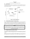
2.4.1 Noise
Due to the variety and the high power of radio equipment often found in today's general
aviation aircraft, there is a potential for both radiated and conducted noise interference.
The KMA 28 power supply is specifically designed to reduce conducted electrical noise
on the aircraft power bus by at least 50dB. Although this is a large amount of attenuation,
it may not eliminate all noise, particularly if the amplitude of noise is very high. There
must be at least 13.8 VDC present at the bottom connector, pin 20, of the KMA 28 for the
power supply to work in its designed regulation. Otherwise, it cannot adequately attenuate
power line noise. Shielding can reduce or prevent radiated noise (i.e., beacon, electric gy-
ros, switching power supplies, etc.) However, installation combinations can occur where
interference is possible. The KMA 28 was designed in a RFI hardened chassis and has
internal Electromagnetic Interference (EMI) filters on all inputs and outputs.
Ground loop noise occurs when there are two or more ground paths for the same signal
(i.e., airframe and ground return wire). Large cyclic loads such as strobes, inverters, etc.,
can inject noise signals onto the airframe that are detected by the audio system. Follow
the wiring diagram very carefully to help ensure a minimum of ground loop potential. Use
only Mil Spec shielded wires (MIL-C-275000, or better).
Radiated signals can be a factor when low level microphone signals are "bundled" with
current carrying power wires. Keep these cables physically separated. It is very important