


Bendix/King
KMA28
Audio Amplifier/Intercom/Marker Beacon Receiver
006-10565-0000 Page 2-3 Rev. 0, Sept. 2000
that you use insulated washers to isolate the ground return path from the airframe to all
headphone and microphone jacks.
2.4.2 Existing KMA-24 Installation
If the installation replaces a KMA-24 (series –00, -01, -02 or -03), the existing 44 pin
connector can be used for the bottom connector of the KMA 28 tray as is, providing it is
properly installed and wired. No other changes are required except for external marker
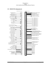
lights (see Appendix B for details). The "key" in the existing connector must be located
between pins 7 and 8. This connector will be used in the bottom connector position. (See
Appendix for complete wiring harness details.)
The existing ground bus may be reused for radio shield connections, if it was constructed
so it can be relocated to the KMA 28 tray.
2.4.3 Existing PS Engineering PMA6000 installations
In 28-Volt aircraft, the dropping resistor may be removed, however, the 2 Amp breaker
should be changed to 3 Amp. If either old unit is stereo (PMA6000S or PMA6000MS),
no rewiring is necessary unless additional features are added.
2.4.3.1 Stereo KMA 28 installations into existing monaural PS Engineering
PMA6000, PMA6000M.
Installations replacing PMA6000 or PMA6000M require re-wiring of the top connector to
accommodate the stereo configuration. See appendixes for detailed interconnect informa-
tion.
2.4.4 Power
The KMA 28 is compatible with both 14 and 28 Volt DC systems. A two (2) Amp circuit
breaker is required for 14 VDC installations, and a three (3) Amp breaker for 28 VDC
aircraft. Power and ground wires must be a twisted #18 AWG pair. Connect airframe
power ground to J1 (bottom connector) Pin Z only. No dropping resistors are required.
2.4.5 Communications Push-to-Talk
An important part of the installation is the PTT (Push-To-Talk) switches that allow the
use of your aircraft communications radio for transmissions. Only the person who presses
their PTT switch will be heard over the radio. If the pilot and copilot both use the PTT,
only the pilot position has access to the radio. The pilot position will have PTT control
regardless of the mic selector switch or copilot PTT when the KMA 28 is in the
EMERGENCY mode.
2.4.6 Transmit Interlock
Some communications transceivers use a transmit-interlock system. To fully utilize the
Split Mode feature, this function must be disabled. Consult that manufacturer's installa-
tion manual.