


Bendix/King
KMA28
Audio Amplifier/Intercom/Marker Beacon Receiver
006-10565-0000 Appendix B Rev. 0, Sept. 2000
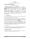
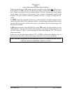
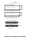
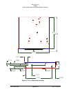
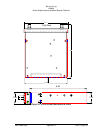
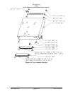
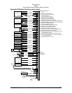
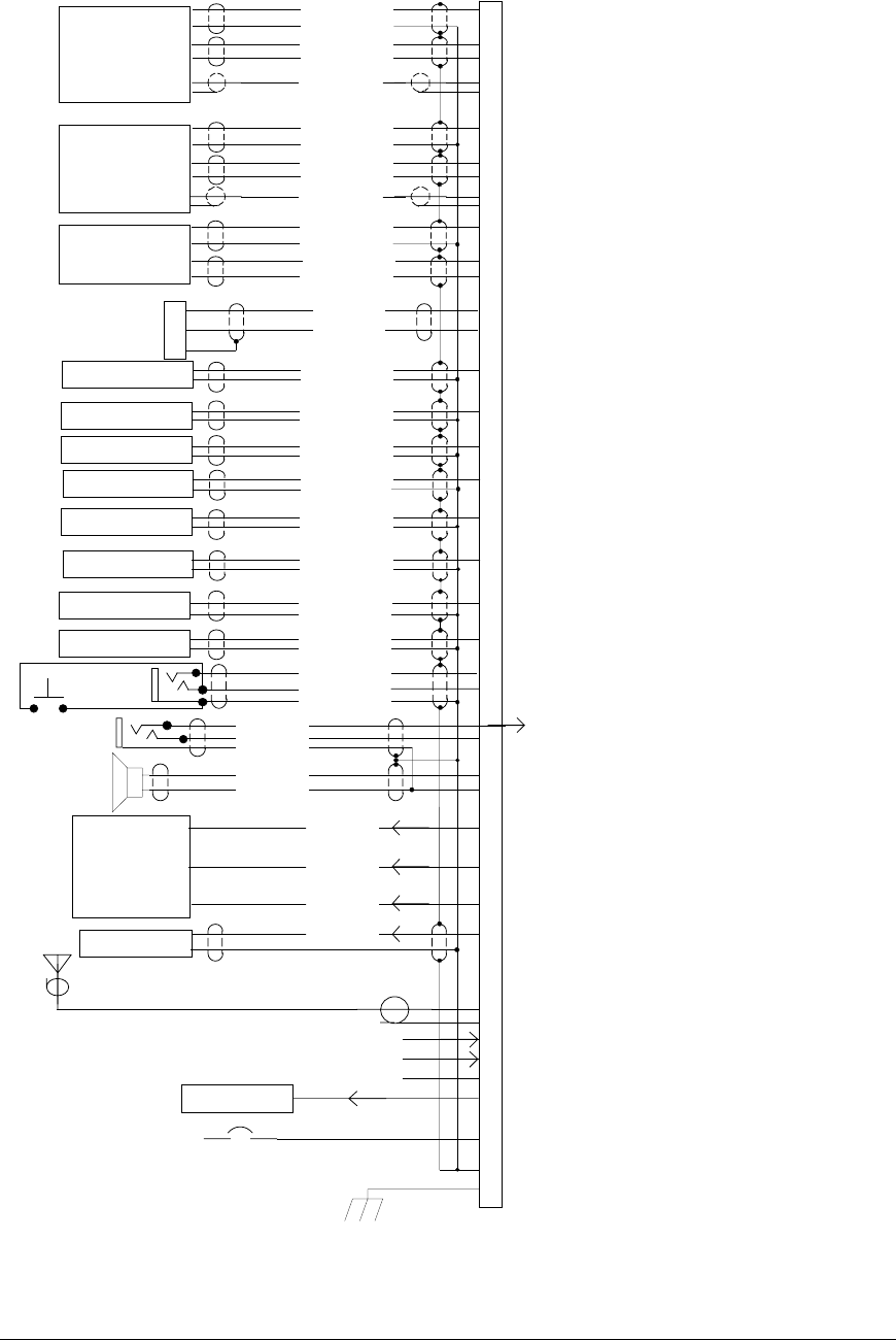
Appendix B Bottom Connector Interconnect
Com 1 Audio Hi
Com 1 Mic Key
Com 1 Lo
Communications
Transceiver #1
Communications
Transceiver #2
Nav 1 Audio Hi
NAV 1 Audio Lo
VHF Nav 1
Nav 2 Audio Hi
Nav 2 Audio Lo
VHF Nav 2
DME Audio Hi
DME Audio Lo
DME Receiver
Com 1 SPR Load
Com 2 SPR Load
Unswitched Input #1 Hi
Unswitched Audio Lo
Unswitched Audio #1
Unswitched Input #2 Hi
Unswitched Audio Lo
Unswitched Audio #2
Pilot Mic Audio Hi
Pilot Mic PTT
Pilot Mic Lo
Ext. Marker Lamp (Blue)
C
5
4
2
Ext. Marker Lamp (White)
Ext. Marker Lamp (Amber)
MM Sense Output
MKR Ant.
B
A
White Lamp Output
Blue Lamp Output
Amber Lamp
MM Sense
RG-400A/U Coax
PA Mute Trigger
F
D
E
18
20
1
Z
W
22
28 Volt Lights Hi
14 V Lights Hi
Lights Lo
Ground
Airframe Ground
2A (14VDC)
3A (28VDC)
11-33 VDC
9
P
R
Com 1 Mic Audio Hi
Com 2 Audio Hi
Com 2 Mic Key
Com 2 Lo
10
H
V
Com 2 Mic Audio Hi
12
13
6
14
N
19
L
Com 1 Spr Load
Com 1 Spr Load
Com 2 Spr Load
Com 2 Spr Load
16
M
T
17
Speaker Hi
Speaker Lo
3
Pilot Phones (L)
Pilot Phones (R)
Pilot Phones Lo
8
Y
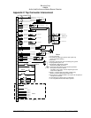
To Pin 1
Top Conn.
Communications
Transceiver #3
J
K
15
Com 3 Audio Hi
Com 3 Mic Audio Hi
Com 3 Lo
Com 3 Mic Key
Mkr Audio In Hi
Mkr Audio In Lo
Ext. Mkr Audio
21
ADF Audio Hi
ADF Audio Lo
ADF Receiver
S
AUX Audio Hi
AUX Audio Lo
AUX Audio
11
Notes:
1. Pins 7, U, and X not used.
2. All shields should be grounded
at audio panel only.
Other end remains floating.
3. Speaker and Pilot Headphone
ground returns MUST be kept
separate and connected to pin 22.
4. All Power, and Ground wires must be #18 gage wire
Lighting #22 AWG, other wires minumum #24 AWG
5. Pilot mic and headphone jacks
must be isolated from ground.
6. Pin 20 connected through a 3 A breaker.
7. PA Mute is a TTL level logic output
that is pulled low when PTT active.
8. Speaker loads may be reqired on some
transceivers. Consult manufacturer's information.
9. 28V installations require a 3 A breaker.
10. Interface information shown for AirCell phone only.
Ground shield at J3 only.
11. All shielded wires must be MIL 22750 or 27500.
12. Connect pilot headphone (L) to top connector, Pin 1,
using 3-conductor wire.
13. Key pin between pin 7 and 8.
Ext. Marker Annunciator
Note 10
Cellphone A
Cellphone B
V
W
K
AirCell
J3
Pilot PTT
See Note 4, 9
See Note 7
See Note 4, 9
See Note 3
See Note 8
See Note 12
Bottom Connector, J1