


Bendix/King
KMA28
Audio Amplifier/Intercom/Marker Beacon Receiver
006-10565-0000 Page 2-10 Rev. 0, Sept. 2000
2.10 Post Installation Checkout
After wiring is complete, verify power is ONLY on pin 20 of the J1 (bottom connector),
and airframe ground on bottom connector pin Z. Failure to do so will cause serious inter-
nal damage and void the warranty.
2.11 Unit Installation
To install the KMA 28, gently slide the unit into the mounting rack until the hold-down
screw is engaged. While applying gentle pressure to the face of the unit, tighten the 3/32"
hex-head in the center of the unit until it is secure. DO NOT OVER TIGHTEN.
Warning: Do not over-tighten the lock down screw while installing the
unit in tray. Internal damage will result.
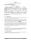
2.11.1 Operational Checkout
1. Apply power to the aircraft and avionics. Switch on the unit by pressing the volume
knob.
2. Plug headsets into the pilot, copilot, and occupied passenger positions.
3. Rotate the Mic Selector Switch to the Com 1 position.
4. Verify that the Com 1 button lights. Verify that the green transmit LED (Light Emit-
ting Diode) near the mic selector is not illuminated. If the LED is on, stop testing and
troubleshoot the microphone PTT installation.
5. Verify proper transmit and receive operation from the copilot position, noting that the
copilot PTT switch allows proper transmission on the selected transceiver.
6. Verify that pushing the COM 2 button causes the button to illuminate, and the Com 2
receiver to be heard. Verify operation on Com 1 from the pilot position.
7. Repeat for Com 2 and Com 3, (if installed).
8. Rotate the mic selector switch to the COM 1/2 position. Verify that the pilot commu-
nicates on Com 1 and the copilot on Com 2.
9. Rotate the mic selector switch to the C
OM 2/1 position. Verify that the pilot commu-
nicates on Com 2 and the copilot on Com 1.
10. Rotate the mic selector switch to the TEL position. Verify that the pilot headset is
connected to the cellular telephone system (if installed). Verify that by using the pilot
side PTT, the pilot can transmit on Com 1. The copilot has no transmit capability in
TEL mode.
11. Verify proper operation of all receiver sources by selecting them using the button.
Note that the button for the receiver sources stays in, and the button illuminates to
show which source is in use.
12. Push in the SPR button. Verify that all selected audio is heard in the cockpit speaker.
Verify that the audio mutes when the mic is keyed.
13. Verify that the LED in the lower right side illuminates when either push to talk is
keyed.
14. Verify proper Intercom system operation in the A
LL, ISO and CREW modes (see Ta-
ble 3-1).