


Bendix/King
KMA28
Audio Amplifier/Intercom/Marker Beacon Receiver
006-10565-0000 Page 2-4 Rev. 0, Sept. 2000
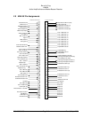
2.4.7 "Swap" Mode
When a momentary, normally open, push-button switch is connected between pin 10 on
the top connector and aircraft ground, the user can switch between Com 1 and 2 by de-
pressing this switch without having to turn the mic selector switch. This yoke-mounted
switch eliminates the need to remove your hands from the yoke to change transceivers.
2.4.8 Backlighting
The KMA 28 has an automatic dimming of the pushbutton annunciator LEDs and marker
lamps controlled by a photocell. Control of the unit backlighting is through the aircraft
avionics dimmer. Connect the dimmer control line to J1 pin D for 14 volt systems, and to
J1 pin F for 28 volt systems. Pin E is light ground.
If an external dimmer control is not used, a constant low level back light illumination can
be established for nighttime viewing. Pin D or F (depending on system voltage) must be
tied to power (J1, pin 20) for the back lighting system to work. The photocell mounted in
the unit face will automatically adjust the intensity of the push-button annunciator LEDs.
2.4.9 Unswitched inputs
J1, pin T is the unswitched input number 1 and J1 pin 17 is unswitched input 2. These
inputs are presented to the pilot and copilot regardless of the audio configuration, and will
always mute the entertainment inputs. These 510Ω inputs can be used for altimeter DH
audio, GPS waypoint audio, autopilot disconnect tones, air-to-ground (Flitefone) tele-
phone ringer or any other critical audio signal. This input is not related to the cellular
telephone interface.
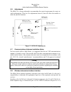
2.4.10 Intercom wiring
The top connector (J2) is for the intercom and additional functions. See Appendix for in-
tercom connection configurations. It is critical to the proper operation of this system to
have this connector wiring made in accordance with these diagrams. Use 2- and 3-
conductor, MIL-spec cable as shown. Connect the shields at the audio panel end only, and
tie to the audio low inputs as shown.
2.4.10.1 Entertainment Input
NOTE: Use the low level output of any entertainment device to connect to
the audio panel. Maximum signal level is 1 VAC p-p.
DO NOT use a speaker-level output, this will cause internal damage in the
audio panel
2.4.10.1.1 Stereo entertainment
Two stereo entertainment devices (CD player, cassette player, etc.) can be connected to
the unit. Install two
1
/
8
-inch stereo jacks in a convenient location so that the pilot can plug